
Floating motor type engine transient dynamic test two-purpose dynamometer and two-purpose method thereof

A dynamic test and engine technology, applied in the direction of power measurement, measuring devices, instruments, etc., can solve the problems of simulating the inertia of the whole vehicle, unable to test the transient performance of the engine, etc., and achieve small size, simple and reliable fixing method, and reduced system inertia Effect

Active Publication Date: 2016-11-16
中检西部检测有限公司
View PDF13 Cites 2 Cited by
  • Summary
  • Abstract
  • Description
  • Claims
  • Application Information

AI Technical Summary

Problems solved by technology

Traditional dynamometers are only used to measure general parameters such as torque and speed, and can only test the parameters of the engine itself, and are generally single-mode (usually transient or steady-state) test dynamometers
With the development of technology and the need to shorten the development cycle, on the one hand, it is necessary to test the transient and steady-state performance of the engine; performance (vehicle speed, acceleration performance, etc.), because the traditional dynamometer cannot accurately simulate the inertia of the vehicle on the bench, the traditional dynamometer cannot meet this requirement, and the dynamic simulation dynamometer cannot be very good engine transient performance test

Method used


Image

  • Floating motor type engine transient dynamic test two-purpose dynamometer and two-purpose method thereof
  • Floating motor type engine transient dynamic test two-purpose dynamometer and two-purpose method thereof
  • Floating motor type engine transient dynamic test two-purpose dynamometer and two-purpose method thereof

Examples


Embodiment Construction

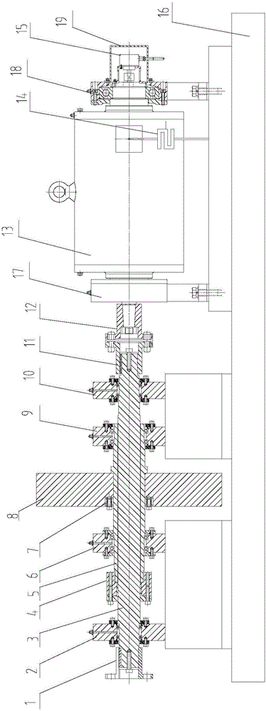
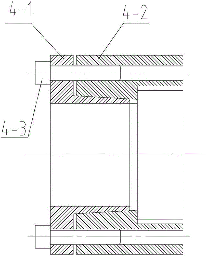
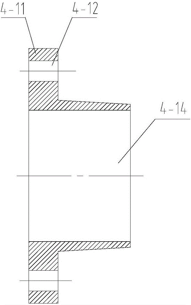
[0048] Such as figure 1 As shown, the floating motor type engine transient dynamic test dual-purpose dynamometer of the present invention includes a base 16 and a first transmission shaft bearing support 2 fixedly connected to the base 16, a second transmission shaft bearing support 10, a first motor Bearing support 17 and second motor bearing support 18, said first transmission shaft bearing support 2 and second transmission shaft bearing support 10 are equipped with transmission shaft 3, and one end of said transmission shaft 3 is connected with transmission shaft engine coupling 1. The other end of the transmission shaft 3 is connected to a transmission shaft motor coupling 11, and a section of the transmission shaft 3 between the first transmission shaft bearing support 2 and the second transmission shaft bearing support 10 is fitted with a flywheel shaft 5, The transmission shaft 3 is connected with the transmission shaft and the flywheel shaft 5 for disconnecting the fly...


PUM


Abstract

The invention discloses a floating motor type engine transient dynamic test two-purpose dynamometer. The floating motor type engine transient dynamic test two-purpose dynamometer comprises a foundation, a first transmission shaft bearing support, a second transmission shaft bearing support, a first motor bearing support and a second motor bearing support, wherein the first transmission shaft bearing support and the second transmission shaft bearing support are equipped with a transmission shaft, the transmission shaft is sleeved with a flywheel shaft, the transmission shaft is connected with a transmission shaft and flywheel shaft connector, the flywheel shaft is connected with an inertia flywheel through a flywheel tension sleeve, a dynamometer motor is arranged between the first motor bearing support and the second motor bearing support, an output shaft of the dynamometer motor departing from the transmission shaft is connected with an encoder, and a casing of the dynamometer motor is provided with a pull pressure transducer. The invention further discloses a two-purpose method of the floating motor type engine transient dynamic test two-purpose dynamometer. The floating motor type engine transient dynamic test two-purpose dynamometer is convenient to realize, realizes low cost, is convenient to mount and use, has complete functions, has high work reliability and stability, has high strong practicality and is convenient for popularization and use.

Description

technical field [0001] The invention belongs to the technical field of engine testing, and in particular relates to a dual-purpose dynamometer for a floating motor type engine transient dynamic test and a dual-purpose method thereof. Background technique [0002] The dynamometer is a device used to measure parameters such as the torque and speed of the engine, electric motor, etc. It is an indispensable test equipment in the engine development test. Traditional dynamometers are only used to measure general parameters such as torque and speed, and can only test the parameters of the engine itself, and are generally single-mode (usually transient or steady-state) test dynamometers. With the development of technology and the need to shorten the development cycle, on the one hand, it is necessary to test the transient and steady-state performance of the engine; performance (vehicle speed, acceleration performance, etc.), because the traditional dynamometer cannot accurately sim...

Claims


Application Information

Patent Timeline
Patent Type & Authority Applications(China)
IPC IPC(8): G01L3/24
CPCG01L3/242
Inventor 杨建伟袁森柱段保民顾怀宁王献民
Owner 中检西部检测有限公司
Learn More