Wind speed sensing device based on fiber bragg gratings, and wind direction monitoring system

A fiber grating, wind speed sensing technology, applied in the direction of speed/acceleration/shock measurement, measurement device, fluid speed measurement, etc., can solve the problems of complicated wind speed sensor device, interference, etc. compact effect

Inactive Publication Date: 2016-11-16
CHANGSHU ZJU INST FOR OPTO ELECTRONICS TECH COMMLIZATION IOTEC
View PDF6 Cites 9 Cited by
  • Summary
  • Abstract
  • Description
  • Claims
  • Application Information

AI Technical Summary

Problems solved by technology

[0005] In order to solve the problem that the wind speed sensing device in the prior art is too complicated and has interference, the present invention proposes a fiber grating-based wind speed sensing device and wind speed and direction monitoring system suitable for various environments with low cost

Method used


Image

  • Wind speed sensing device based on fiber bragg gratings, and wind direction monitoring system
  • Wind speed sensing device based on fiber bragg gratings, and wind direction monitoring system
  • Wind speed sensing device based on fiber bragg gratings, and wind direction monitoring system

Examples


Embodiment 1

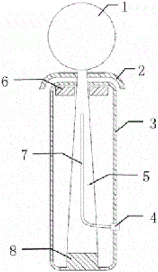
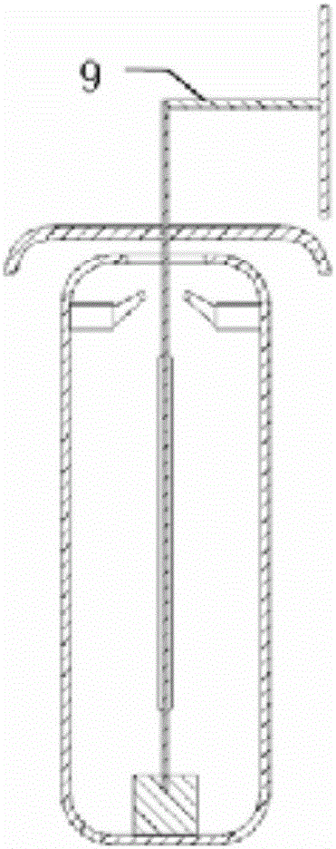
[0033] The present invention relates to a schematic structural diagram of a wind speed sensing device based on a fiber grating such as figure 1 with figure 2 shown. The wind speed sensing device includes: a circular windward pressure plate 1 , a cantilever beam of equal strength 5 , a dust cover 2 , an optical fiber grating 7 , an optical fiber adapter 4 , a self-heating device 6 and a packaging shell 3 . The windward pressure plate 1 is welded to the top of the equal-strength cantilever beam 5 through the connecting rod 9; the equal-strength cantilever beam 5 is fixed on the base of the packaging shell 3, and an optical fiber Bragg grating is welded on the central axis of the front and back surfaces of the beam, respectively. Located in the 850nm wavelength band, in order to ensure that the fiber grating is evenly stressed, the equal-intensity beam 5 is designed in the shape of an isosceles triangle within the effective force-bearing range. The grating pigtail passes throu...

Embodiment 2

[0045] Figure 5 It is an example diagram of the wind speed and wind direction monitoring system proposed based on the wind speed sensing device, including two above-mentioned fiber grating wind speed sensors, optical fiber jumpers, wavelength demodulation equipment and remote control computer four parts. Two fiber grating wind speed sensors are placed orthogonally to measure the projected components of the wind speed in two vertical directions, and finally the wind direction information can be obtained through geometric synthesis calculation. The detection signals of the two sensors are sent to the remote wavelength demodulation device through the optical fiber jumper. In order to reduce the cost and simplify the system in the present invention, the wavelength information of the fiber Bragg grating is converted into the optical signal intensity for demodulation, and then the wind speed and direction information is calculated according to the corresponding model. Finally, the...


PUM


Abstract

The invention discloses a wind speed sensing device based on fiber bragg gratings, and a wind direction monitoring system. The device comprises a wind energy transmission mechanism, a constant strength cantilever beam, and a packaging housing. The wind energy transmission mechanism consists of a windward pressed plate and a connecting rod, wherein the connecting rod is perpendicular to the windward pressed plate. One end of the windward pressed plate is fixed at the center of the connecting rod, and the other end of the windward pressed plate is fixed at the top of the constant strength cantilever beam. The top of the packaging housing is provided with an opening, and a cantilever beam installation pedestal is fixed at the bottom of the interior of the packaging housing. The constant strength cantilever beam stretches into the opening at the top of the packaging housing, and is detachably fixed on the cantilever beam installation pedestal. The surface of the windward pressed plate is parallel to the surface of the constant strength cantilever beam. The axes of the front and back surface of the constant strength cantilever beam are respectively provided with one fiber bragg grating. The system comprises two wind speed sensing devices which are arranged in an orthogonal manner, and the measured data is transmitted to a remote terminal. The device is compact in structure, is small in size, and is resistant to electromagnetic interference.

Description

technical field [0001] The invention belongs to the technical field of optical fiber sensing, and in particular relates to an optical fiber grating-based wind speed sensing device and a wind speed and direction monitoring system. Background technique [0002] The monitoring of wind speed and direction plays an important role in the fields of weather forecast, power system, aviation and navigation, and agricultural production. At present, such sensors mainly include: mechanical type (wind cup type), electronic type (hot wire type, ultrasonic type, Doppler translation type) and pitot tube type. In the actual application process, there are the following problems: the mechanical type is easy to wear and is affected by inertia, and the measurement accuracy and timeliness are not good; the electronic type is vulnerable to electromagnetic interference in harsh electromagnetic environments; and the pitot tube can only measure wind speed , the wind direction cannot be monitored. At...

Claims


Application Information

Patent Timeline
Patent Type & Authority Applications(China)
IPC IPC(8): G01P5/26G01P13/02
CPCG01P5/26G01P13/02
Inventor 严国锋何赛灵
Owner CHANGSHU ZJU INST FOR OPTO ELECTRONICS TECH COMMLIZATION IOTEC
Why Eureka
Try Eureka