Sonar array laying method and system

An array and sonar technology, applied in the field of underwater sonar array deployment, can solve problems such as slow speed and poor anti-interference ability, and achieve the effect of reducing the impact of acquisition equipment, strong anti-interference ability, and expanding working range

Inactive Publication Date: 2016-11-16
武汉普惠海洋光电技术有限公司 +1
View PDF8 Cites 4 Cited by
  • Summary
  • Abstract
  • Description
  • Claims
  • Application Information

AI Technical Summary

Problems solved by technology

[0006] In order to solve the problems of slow speed and poor anti-interference ability in the existing sonar array deployment method, the present invention discloses a sonar array deployment method and system, which realizes the rapid deployment of the sonar array , sonar array data acquisition system and signal processing system are separated to work at a long distance; the present invention enables shore-based or ship-borne staff to know in real time the original data and acquisition nodes picked up by the sonar array data acquisition system in the case of a long distance At the same time, it reduces the interference of the acquisition equipment by the noise of the nearby support platform, improves the signal-to-noise ratio of the acquisition data, and can also reduce the impact of the support platform jitter on the acquisition equipment, and also expands the working range of the sonar array, such as shore, island Inter-chain, etc., protecting the original target detection ability of the sonar array

Method used


Image

  • Sonar array laying method and system
  • Sonar array laying method and system
  • Sonar array laying method and system

Examples


Embodiment 1

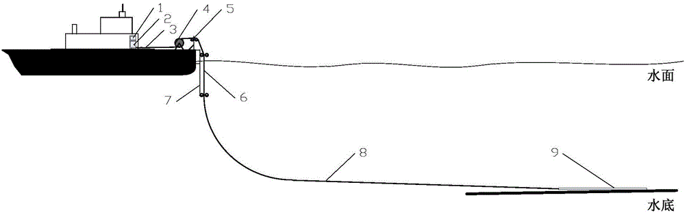
[0036] Such as figure 1 , 3 , 4, 6, and 8, the present invention discloses a deployment method of a sonar array, the deployment method comprising:

[0037] Step 1, the deployment mechanism is mounted on the surface ship, the sonar array 9 is connected to the optical cable 8, and the sonar array 9 connected to the optical cable 8 is deployed on the bottom of a certain water area through the deployment mechanism;

[0038] Step 2, then, according to the characteristics of the optical cable 8 such as tensile strength, small outer diameter, and small loss, the surface ship with a deployment mechanism moves forward while laying the optical cable 8;

[0039] Step 3: After the surface ship travels several kilometers or tens of kilometers, the deploying mechanism arrives at the designated position to make the surface ship drift and be on duty.

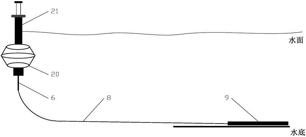
[0040] Step 4, connect the optical fiber connector carried by at least one surface ship to the submersible buoy or buoy, and then use the su...

Embodiment 2

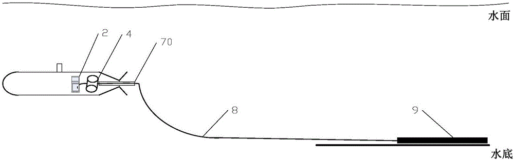
[0046] Such as figure 2 , 3 , 5, 7, and 8, the deployment method and system of the sonar array of Embodiment 2 are basically the same as Embodiment 1, and the difference is that: figure 2 As shown, in this embodiment, the deployment mechanism is installed on the underwater unmanned submersible. The deployment mechanism includes a signal processor 2, a winch 4 and a cable guide 70, and the optical cable 8 passes through the cable guide 70 and winds the winch 4 After that, it is connected with the signal processor 2.

[0047] The deployment method of this embodiment includes:

[0048] Step 1, the deployment mechanism is mounted on the underwater unmanned submersible, the sonar array 9 is connected to the optical cable 8, and the sonar array 9 connected to the optical cable 8 is deployed on the bottom of a certain water area through the deployment mechanism;

[0049] Step 2, then, relying on the characteristics of the optical cable 8 such as tensile strength, small outer dia...


PUM


Abstract

The invention discloses a sonar array laying method and system. The method comprises a step 1 of connecting a sonar array with an optical cable, and placing the sonar array connected with the optical cable on the bottom of a water area by a laying mechanism, a step 2 of the laying mechanism moving forward while laying the optical cable, and a step 3 of the laying mechanism starting an attendant state after arriving at an assigned position. The system comprises a laying mechanism and an optical cable, wherein a fiber joint at one end of the optical cable is carried by the laying mechanism, and a fiber joint at the other end of the optical cable is connected with the sonar array. The rapid sonar array laying problem in practical application is well solved, remote separate operation of a sonar array data collection system and a signal processing system is achieved, interference from surrounding support platform noise on collection equipment is reduced, the signal to noise ratio is raised, influences of support platform jitter on the collection equipment are reduced, and the working range of the sonar array is expanded.

Description

technical field [0001] The invention relates to the technical field of underwater sonar array deployment, more specifically, a method and system for deploying a sonar array. Background technique [0002] At present, radio communication and underwater acoustic communication are mainly used for ship-borne and submerged buoy communication. Among them, the attenuation of radio increases with the increase of frequency underwater. Without the help of external sensors such as towed antennas and buoys, ship-borne and submersible buoys can use ultra-long-wave and very-long-wave signals, so that ship-borne and submersible buoys can operate at depths exceeding 100 Receive communication signals from the shore to ship-borne and submerged buoys when the depth of the sea is 25 to 30 meters or submerged 25 to 30 meters. However, there are many problems in underwater acoustic communication, such as large delay, limited bandwidth, high bit error rate, high energy consumption, etc. [0003] ...

Claims


Application Information

Patent Timeline
IPC IPC(8): G01S15/02
CPCG01S15/02
Inventor 张海兵余华兵
Owner 武汉普惠海洋光电技术有限公司
Why Eureka
Try Eureka