Power distribution cabinet structure

A technology for power distribution cabinets and cabinets, applied in substation/power distribution device shells, electrical components, substation/switch layout details, etc.

Active Publication Date: 2016-11-16
广东正超电气有限公司
View PDF2 Cites 4 Cited by
  • Summary
  • Abstract
  • Description
  • Claims
  • Application Information

AI Technical Summary

Problems solved by technology

However, when the external environment is high temperature and high humidity, it is not suitable to use heating for dehumidification, and there are obviously technical defects.

Method used


Image

  • Power distribution cabinet structure
  • Power distribution cabinet structure
  • Power distribution cabinet structure

Examples


Embodiment 1

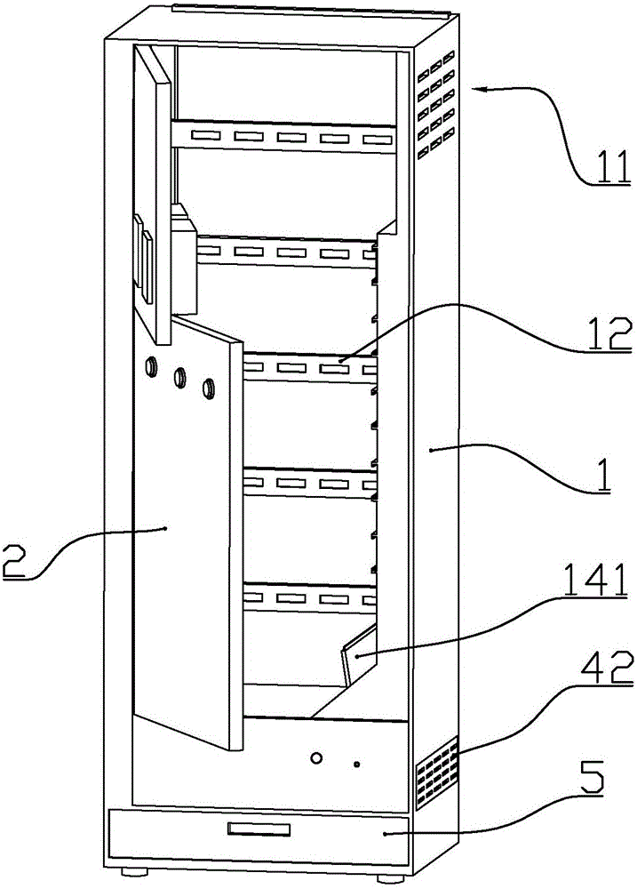
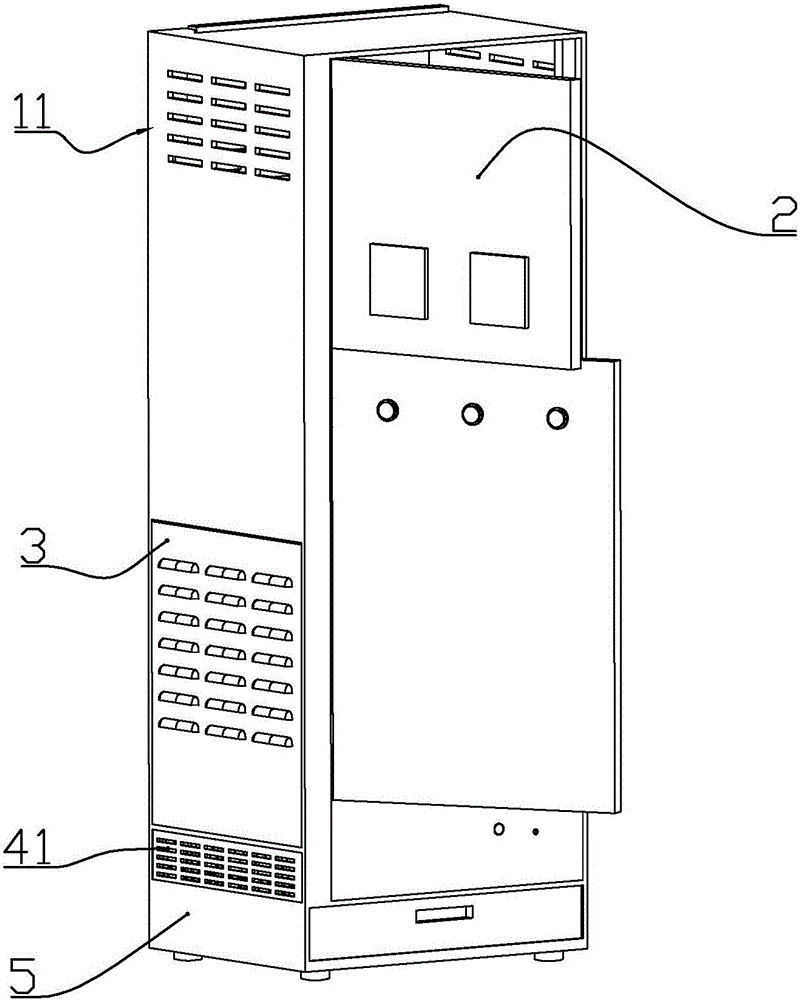
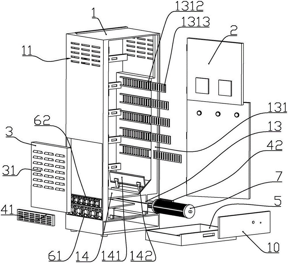
[0066] according to Figure 1 to Figure 13 As shown, this embodiment is a power distribution cabinet structure, including a cabinet body 1 with an open front end, and a cabinet door 2 connected to the front end of the cabinet body through hinges; multiple sets of horizontally arranged cabinets are installed at the rear of the cabinet body. Mounting frames 12; the mounting frames are arranged equidistantly along the vertical direction; air outlets 11 are formed on the left and right sides of the upper part of the cabinet.

[0067] The bottom of the cabinet body is formed with a slope plate 16 that is high on both sides and low in the middle; in the cabinet, the rear side of the cabinet is the rear cabinet, and the bottom of the rear cabinet is located above the middle of the slope. A stepper motor 8 is installed. The output shaft of the stepping motor is connected with a cooling plate assembly 7 arranged horizontally along the front and back direction of the cabinet.

[0068] ...

Embodiment 2

[0083] according to Figure 1 to Figure 13 As shown, this embodiment is a power distribution cabinet structure, including a cabinet body 1 with an open front end, and a cabinet door 2 connected to the front end of the cabinet body through hinges; multiple sets of horizontally arranged cabinets are installed at the rear of the cabinet body. Mounting frames 12; the mounting frames are arranged equidistantly along the vertical direction; air outlets 11 are formed on the left and right sides of the upper part of the cabinet.

[0084] The bottom of the cabinet body is formed with a slope plate 16 that is high on both sides and low in the middle; in the cabinet, the rear side of the cabinet is the rear cabinet, and the bottom of the rear cabinet is located above the middle of the slope. A stepper motor 8 is installed. The output shaft of the stepping motor is connected with a cooling plate assembly 7 arranged horizontally along the front and back direction of the cabinet.

[0085] ...


PUM

PropertyMeasurementUnit
Widthaaaaaaaaaa
Apertureaaaaaaaaaa

Abstract

The invention discloses a power distribution cabinet structure, which comprises a cabinet body with an opening in the front end and a cabinet door connected to the front end of the cabinet body through hinges; a slope plate which is high in the middle part and low in two sides is formed at the bottom part in the cabinet body; a stepper motor is arranged at the lower part of a rear cabinet plate at the rear side of the cabinet body above the middle position of the slope plate in the cabinet body; an output shaft of the stepper motor is connected with a refrigeration piece assembly which is horizontally arranged along the frontward-backward direction of the cabinet body; a front baffle plate is arranged at the lower part of the front side of the cabinet body; a first flow guide plate is fixedly connected to the left upper part of the refrigeration piece assembly in the cabinet body; the left side and the right side of the refrigeration piece assembly in the cabinet body are rotationally connected with a front wind deflector and a rear wind deflector respectively; an upper air inlet is formed, between the first flow guide plate and a second flow guide plate, in the left side of the cabinet body; an upper fan is arranged in the upper air inlet; the outer wall on the left side of the cabinet body is connected with an upper air inlet plate above the upper air inlet; and exhaust openings are formed in the left side and the right side of the upper part of the cabinet body. The power distribution cabinet structure is simple and compact and suitable for use in various complicated working environments.

Description

technical field [0001] The invention belongs to the field of electric equipment, and in particular relates to a structure of a power distribution cabinet. Background technique [0002] The power distribution cabinet is to assemble switchgear, measuring instruments, etc. in a closed or semi-closed metal cabinet according to the requirements of electrical wiring. The Chinese patent with the document number CN104613672A discloses a semiconductor high-voltage cabinet dehumidification device. The shape of the invention is a sheet-like body made of semiconductor refrigeration sheets, and its heating surface is attached to the high-voltage power distribution cabinet through heat-conducting silicone grease. On the inner wall of the metal shell, its cooling surface is close to a layer of metal film. The outer surface of the metal film is a polished plane. There is an inclined bus bar on the plane. The bus bar leads to the high-voltage power distribution through the return pipe. outs...

Claims


Application Information

Patent Timeline
IPC IPC(8): H02B1/56H02B1/32H02B1/28
CPCH02B1/28H02B1/32H02B1/565
Inventor 周佳斌
Owner 广东正超电气有限公司
Why Eureka
Try Eureka