
Balloon dilatation catheter for interruption

A technology for dilating catheters and balloons, which is applied in the fields of drug devices, devices introduced into the body, medical science, etc. It can solve the problems of incomplete contact between drugs and blood vessel walls, and the lack of therapeutic and preventive effects of blood vessel walls, so as to reduce drug complications. Symptoms, reduced drug dose, increased function

Inactive Publication Date: 2016-11-23
谷涌泉
View PDF4 Cites 6 Cited by
  • Summary
  • Abstract
  • Description
  • Claims
  • Application Information

AI Technical Summary

Problems solved by technology

At present, there is a blocking balloon in foreign countries. First, the balloon dilation catheter is inserted into the blood vessel through a small incision, and the balloons at the front and rear ends of the balloon dilation catheter are used to expand the two ends of the blood vessel at the site to be blocked. Then, through the micro-holes on the catheter wall between the two balloons, the current commonly used drugs are injected to treat the segment of blood vessels; however, because the drugs are not in close contact with the blood vessel wall, these drugs can only It has a certain effect on intravascular lesions (such as thrombus), but has little therapeutic and preventive effect on blood vessel walls (intimal hyperplasia)

Method used


Image

  • Balloon dilatation catheter for interruption
  • Balloon dilatation catheter for interruption
  • Balloon dilatation catheter for interruption

Examples


Embodiment Construction

[0019] The present invention will be described more fully below using examples. This invention may be embodied in many different forms and should not be construed as limited to the exemplary embodiments set forth herein.

[0020] For ease of description, spatially relative terms such as "upper," "lower," "left," and "right" may be used herein to describe the relationship of one element or feature relative to another element or feature shown in the figures. It will be understood that the spatial terms are intended to encompass different orientations of the device in use or operation in addition to the orientation depicted in the figures. For example, if the device in the figures is turned over, elements described as "below" other elements or features would then be oriented "above" the other elements or features. Thus, the exemplary term "lower" can encompass both an orientation of above and below. The device may be otherwise oriented (rotated 90 degrees or at other orientatio...


PUM


Abstract

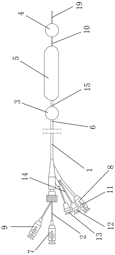
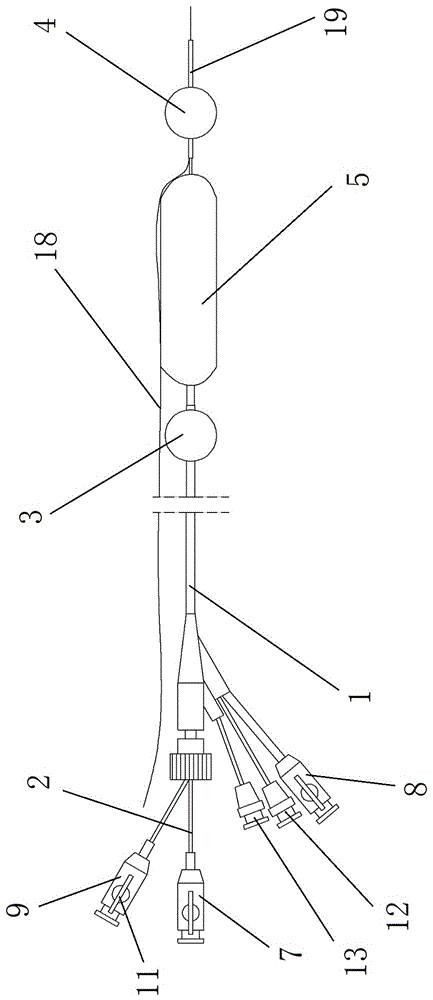
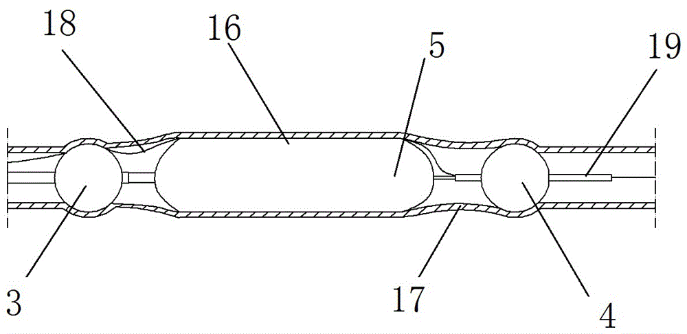
The invention discloses a blocked balloon dilation catheter. The front end of the balloon dilation catheter is a working area, the rear end of the working area is provided with a first blocking balloon, and the front end of the working area is provided with a second blocking balloon. Balloons, a drug administration micropore is arranged between the two blocking balloons, and the drug administration micropore is close to one of the blocking balloons; a working ball is arranged between the drug administration micropore and the balloon far away from the drug administration micropore A balloon, the effective length of the working balloon is greater than half of the distance between the drug delivery microhole and the balloon away from the drug delivery microhole. The blocked balloon dilation catheter of the present invention arranges a working balloon between the two balloons at the front end of the balloon dilation catheter, and squeezes the closed space between the two balloons into a thin-walled annular columnar shape, reducing At the same time, before removing the blocking, the pressure of the working balloon is released, and the diluent is added to dilute the liquid medicine, so as to avoid the damage of the high-concentration liquid medicine to the organs.

Description

technical field [0001] The invention relates to a blood vessel surgical instrument, in particular to a blocked balloon dilation catheter. Background technique [0002] With the advancement of technology, minimally invasive surgery has been developed rapidly. In interventional surgery, local blood vessels need to be blocked, and the use of balloon dilatation catheters instead of vascular clamps can effectively prevent damage to blood vessel walls. At present, there is a blocking balloon in foreign countries. First, the balloon dilation catheter is inserted into the blood vessel through a small incision, and the balloons at the front and rear ends of the balloon dilation catheter are used to expand the two ends of the blood vessel at the site to be blocked. Then, through the micro-holes on the catheter wall between the two balloons, the current commonly used drugs are injected to treat the segment of blood vessels; however, because the drugs are not in close contact with the ...

Claims


Application Information

Patent Timeline
Patent Type & Authority Applications(China)
IPC IPC(8): A61B17/12A61M5/14
CPCA61B17/12045A61B17/12109A61B17/12136A61M5/14A61M2202/0468
Inventor 谷涌泉
Owner 谷涌泉
Learn More