
Force couple type telescopic clamping device of manipulator

A technology of a clamping device and a telescopic device, which is applied in the field of manipulators, can solve the problems of the connection between the clamping device and the arm being easily damaged, the control system is complex, and the space is large, and the time required for loading and unloading materials is short and the positioning accuracy is high. , the effect of improving production efficiency

Pending Publication Date: 2016-11-23
重庆科菲精密机械有限公司
View PDF6 Cites 4 Cited by
  • Summary
  • Abstract
  • Description
  • Claims
  • Application Information

AI Technical Summary

Problems solved by technology

In order to reserve the working space for the operator, the working lines of the truss manipulator are all on the top of the CNC machine tool, which leads to the large space occupied by the truss manipulator, the distance between the loading and unloading station and the spindle chuck processing station, the long feeding auxiliary time, and poor maintenance. convenient
[0004] 2) The multi-joint manipulator is more similar to manual operation. The multi-joint manipulator has high motion precision, high processing and manufacturing costs, its control system is complicated, and the multi-joint manipulator is expensive
In order to facilitate the grasping of the workpiece, the arm of the multi-joint manipulator is usually relatively long. When the arm drives the workpiece to swing together, the swing distance is long, that is, the stroke is long. The joints are easily damaged and the maintenance cost is high
For precision machining machine tools, the damage of the multi-joint manipulator makes it impossible for the clamping device to accurately position the workpiece on the spindle chuck of the machine tool; and the inertia is large, resulting in large wear between the workpiece and the spindle chuck of the machine tool, resulting in damage to

Method used


Image

  • Force couple type telescopic clamping device of manipulator
  • Force couple type telescopic clamping device of manipulator
  • Force couple type telescopic clamping device of manipulator

Examples


Embodiment Construction

[0021] The present invention will be further described below in conjunction with the accompanying drawings.

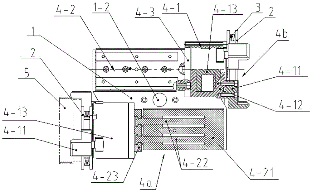
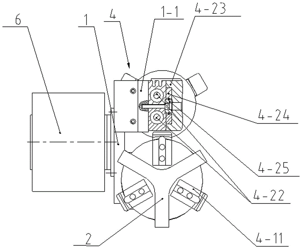
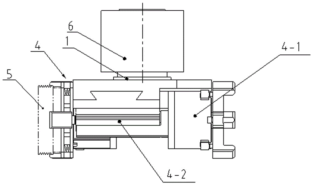
[0022] see Figure 1 to Figure 4 The shown force couple telescopic clamping device of a manipulator includes a mounting bracket 1 for installation on the manipulator, and a pair of telescopic clamping devices 4 arranged symmetrically with the center of the mounting bracket 1 are fixed on the mounting bracket 1 , one of which is a telescopic clamping device 4a for feeding, and the other is a telescopic clamping device 4b for unloading, and the pair of telescopic clamping devices 4 are all composed of telescopic device 4-2 and telescopic device 4 -2 connected clamping claws 4-1, the telescopic device 4-2 is used to drive the clamping claws 4-1 to extend outwards and retract inwards, and the clamping claws 4-1 are used For clamping and loosening the workpiece; the axes of the telescopic clamping device 4a for loading and the telescopic clamping device 4b for unloading ar...


PUM


Abstract

The invention discloses a force couple type telescopic clamping device of a manipulator. The force couple type telescopic clamping device of the manipulator comprises a mounting bracket, wherein the mounting bracket is used for being mounted on the manipulator; one pair of telescopic clamping devices which are formed to have a central symmetrical layout according to the center of the mounting bracket are fixedly arranged on the mounting bracket; the telescopic clamping devices consist of telescopic devices and clamping paws connected with the telescopic devices; the telescopic devices are used for driving the clamping paws to extend outwards and to retract inwards; the clamping paws are used for pinching or loosening a work piece; one of the telescopic clamping devices is a telescopic clamping device used for charging, while the other of the telescopic clamping devices is a telescopic clamping device used for discharging; the axial leads of the telescopic clamping device used for the charging and the telescopic clamping device used for the discharging are parallel to each other; and further, the orientations of pinching paws of the telescopic clamping device used for the charging and the telescopic clamping device used for the discharging are opposite. The force couple type telescopic clamping device provided by the invention is small and exquisite in structure, uniform in load and long in service life.

Description

technical field [0001] The invention relates to a manipulator, in particular to a force couple telescopic clamping device for the manipulator. Background technique [0002] Traditional machine tools are loaded and unloaded manually. This method has many problems such as high labor intensity, low efficiency, poor safety, and high labor cost. With the development of science and technology and the increase of labor costs, it has become an inevitable trend in the field of mechanical processing to adopt automatic operation means to reduce labor intensity and improve production efficiency. To realize the automatic processing of CNC machine tools, it is inseparable from the manipulators of CNC machine tools. At present, there are the following types of manipulators that are used in conjunction with CNC machine tools on the market: [0003] 1) The truss manipulator, after the clamping device of the truss manipulator clamps the workpiece to be processed on the workpiece conveying li...

Claims


Application Information

Patent Timeline
Patent Type & Authority Applications(China)
IPC IPC(8): B23Q7/04
CPCB23Q7/043
Inventor 徐绍林
Owner 重庆科菲精密机械有限公司
Learn More