Multifunctional operation type underwater robot

An underwater robot, multi-functional technology, applied in the direction of underwater operation equipment, ships, ship salvage, etc., to achieve the effect of large range, strong cross-country ability, and convenient salvage

Inactive Publication Date: 2016-11-23
QINGDAO SEA ROBOT CO LTD
11 Cites 38 Cited by

AI-Extracted Technical Summary

Problems solved by technology

However, the existing robots cannot be fixed well, and drift due to ...

Method used

Adopt compressed air bag 411 to also have two advantages: the one, the compressed air in compressed air bag 411 is isolated from ballast water, can not cause the phenomenon of exhaust and non-drainage because of underwater robot posture reversal, no matter what posture, get rid of It's all ballast water. Compared with ordinary water tanks, there is no air bag in it, so when it is turned over, opening the water valve will discharge lighter compressed air, leaving the ballast water in the water tank, so that the underwater robot will not only be unable to float, Instead, it sinks faster. The 2nd, according to working water depth, can charge and release the compressed air of different air pressure, keep the ballast water in the compressed air bag 411 higher than the external suitable working water pressure all the time. If the air pressure is too low, the gas in the compressed air bag 411 will not be able to withstand the external water pressure, and the ballast water will not be discharged, and the float will fail. Too high air pressure in the compressed airbag 411 will increase the cost and even damage the water valve of the airbag. Ballast water tank housing 41 , compressed air bag 411 , air bag cover 412 , water inlet valve 413 , and drain valve 414 . By controlling the compressed air bag 411, the water inlet valve 413, and the drain valve 414, the weight of the underwater robot can be well controlled, and then the cargo capacity can be well controlled.
The manipulator 12 is configured on the top of the equipment, which can be designed longer, so that the space is not restricted during the rotation operation, and the active area of ​​salvage and collection is just larger, and the production efficiency is just much higher. When flying on the bottom of the sea, it can be rotated to the back end to move forward, reducing the head-on-water sur...

Abstract

A multifunctional operation type underwater robot comprises a picking device, driving devices, camera shooting and illumination devices, floating devices, a walking device and a shell. The picking device is arranged on the top of the shell. The four corners and the tail of the shell are provided with the driving devices. The floating devices are distributed at the four corners and the two sides of the shell. The camera shooting and illumination devices are fixed to the picking device and the shell. The walking device is arranged at the lower portion of the shell. The underwater robot has the function of accurate seabed positioning, has the advantages of facilitating fishing and being large in range, meanwhile, can dynamically adjust buoyancy and is strong in cross-country capacity.

Application Domain

Vessel salvagingUnderwater equipment

Technology Topic

EngineeringSeabed +5

Image

  • Multifunctional operation type underwater robot
  • Multifunctional operation type underwater robot
  • Multifunctional operation type underwater robot

Examples

  • Experimental program(1)

Example Embodiment

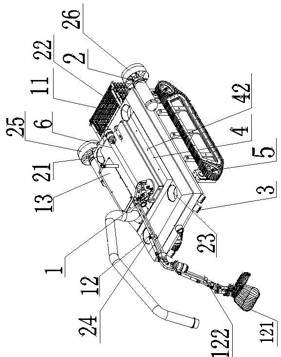
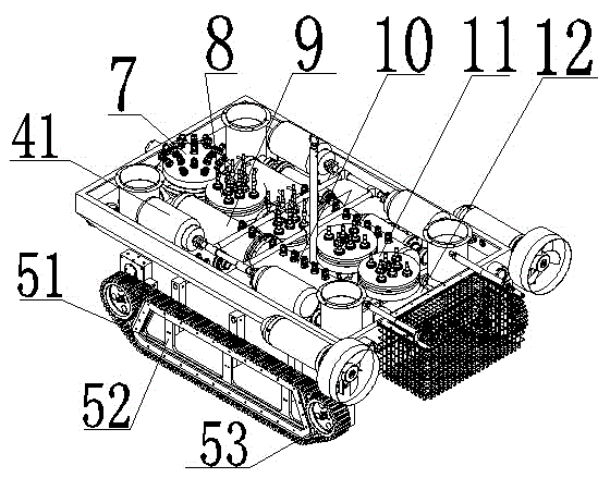
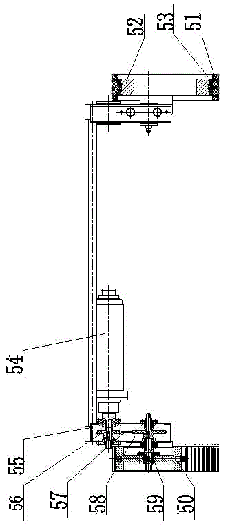
[0022] As shown in the figure, a multifunctional underwater robot includes a pickup device 1, a driving device 2, a camera and lighting device 3, a sink and float device 4, a walking device 5, and a housing 6. The pickup device 1 is placed in the housing. At the top of the body 6, the four corners and the tail of the housing 6 are provided with a driving device 2; the sink and float devices 4 are distributed on the four corners and both sides of the housing 6; the camera and lighting device 3 is fixed on the pickup device 1 and the housing 6; The walking device 5 is placed in the lower part of the housing 1.
[0023] Further, the pick-up device 1 includes a manipulator 12 used in conjunction with the collection basket 11 and a suction filter box 13 disposed on the upper part of the housing 6. The manipulator 12 includes a mechanical grip 121 and a mechanical grip connected to the mechanical grip 121 The arm 122, the mechanical arm 122 is a hydraulic structure, the hydraulic cylinder is pneumatic or hydraulic, the mechanical grip 121 can be a bucket or a hand pliers; the suction filter box 13 includes a filter box body 131 and a water suction pump 132, the suction pipe 133, the suction pipe connecting plate 134, and the tank cover 135. The suction pump 132 is placed at the bottom of the lower part of the filter box body 131. The suction pipe 133 is connected to the suction pump 132 through the suction pipe connecting plate 134.
[0024] Further, the driving device 2 includes four vertical propulsion propellers 21, 22, 23, 24 respectively placed at the four corners of the housing 6, and two horizontal propulsion propellers 25, 26 placed on the rear side of the housing; the propellers are both It can act alone, the propellers rotate in both positive and negative directions and can independently adjust the speed at will.
[0025] Further, the sinking and floating device 4 includes a ballast water tank 41 with a compressed air bag 411 and a buoyancy block 42 arranged between the vertical propulsion propellers 21, 22, 23, 24; the compressed air bag 411 is connected to the inlet through a solenoid valve The water valve module 14 and the water outlet valve module 15 are connected; the buoyancy blocks 42 are respectively placed on the left and right sides of the upper shell 6. The sink and float device 4 can individually control each air content to control the underwater robot to maintain any posture, and dynamically adjust the up and down buoyancy according to the cargo load.
[0026] Further, the walking device 5 includes a crawler-type crawler chassis 51, the crawler chassis 51 includes a hollow crawler guide frame 52, and a sliding guide bar 53 is arranged on the crawler guide frame 52. The crawler chassis 51 increases the ground clearance through a chain transmission structure. The walking device 5 also includes a driver 54, a drive box 55, a small drive sprocket 56, a drive chain 57, a passive dalian wheel 58, a crawler axle 59, a crawler wheel 50 and so on.
[0027] Further, the imaging and lighting device 3 includes a camera 31 and a lighting lamp 32 provided on the manipulator 12 for use, and a camera 31 and a lighting lamp 32 provided on the front side of the casing 6 for use.
[0028] Further, it also includes a main control bin 7, a water inlet valve module 8, a battery bin 9, a sub-control bin 10, a water outlet valve module 11, and a high-pressure submersible pump 12 arranged in the housing 6. The main control bin 7 is provided with Attitude gyroscope.
[0029] The underwater robot is equipped with four vertical thrusters 21, 22, 23, 24 and two larger horizontal thrusters 25, 26. When flying underwater, it can achieve six degrees of freedom movement. Three translational movements are forward and backward, ascent and Side shift; the three rotary motions are steering, pitching and rolling. The design uses four vertical propellers 21, 22, 23, 24 to propel in the opposite direction so that the crawler can be firmly attached to the seabed, any slope or hull. At the same time, when there is a large reef or a large obstacle in the front, the vertical thruster 21, 22, 23, 24 can be controlled to achieve climbing, vertical lifting, and rolling to overcome the obstacle. When moving horizontally, it mainly depends on two large horizontal propellers 25 and 26 arranged horizontally.
[0030] Let the four vertical propellers 21, 22, 23, 24 spray water upwards to form a reaction force pressing against the crawler chassis 51, which can make the crawler reliably close to the seabed or slope surface, or even turn over to close to the bottom of the ship, thus driving the crawler , It can reliably make the crawler drive the underwater robot to move left, right, front, back and turn.
[0031] The ballast water tank 11 can dynamically adjust its own buoyancy according to the cargo situation (the compressed air bag 411 is provided in the ballast water tank 41), and according to the depth of water entry, it can be filled with gas of different pressures to adapt to underwater pressure and ballast water. With the increase of the catch on the seabed, the buoyancy in the water will become smaller and smaller, and it will be difficult to encounter large slopes or obstacles. This is to open the solenoid valve, and the compressed airbag 411 will remove the right amount of pressure. Carry water, compensate the weight of the cargo, and continue to keep the underwater robot at zero buoyancy, so that the underwater robot can continue to move flexibly until it is fully loaded.
[0032] There are two more advantages to using the compressed airbag 411: First, the compressed air in the compressed airbag 411 is isolated from the ballast water, and there will be no undrained exhaust due to the overturning of the underwater robot's attitude. No matter what the attitude is, what is eliminated is the pressure. Carry water. Compared with ordinary water tanks, there is no air bag in it. When it is turned over, lighter compressed air will be discharged when the water valve is opened, leaving the ballast water in the tank. This will cause the underwater robot to not only not float up, but also Instead, it accelerates sinking. Second, according to the working water depth, compressed air of different pressures can be charged and discharged, and the ballast water in the compressed air bag 411 is always kept higher than the suitable working water pressure outside. If the air pressure is too low, the compressed airbag 411 cannot resist the external water pressure. If the ballast water cannot be discharged, the floating will fail. Too high air pressure of the compressed airbag 411 will increase the cost and even destroy the airbag water valve. Ballast water tank shell 41, compressed air bag 411, air bag cover 412, water inlet valve 413, and drain valve 414. By controlling the compressed airbag 411, the water inlet valve 413, and the drain valve 414, the weight of the underwater robot can be well controlled, and the cargo load can be well controlled.
[0033] At the same time, the amount of ballast water in the ballast water tank 41 can be separately adjusted according to needs, so that different postures of the underwater robot in the water can be maintained. Set an attitude gyroscope 71 in the main control compartment 7 to feel the attitude change angle and set parameters arbitrarily. If the left front corner is tilted, the ballast water tank 41 in the left front corner can be made less ballast water, and the other three remain unchanged; another example is to raise the tail of the aircraft and the nose sinks, and the entire fuselage is vertical in the water. In the straight state, the first two ballast water tanks 11 can be filled with more water, and the rear two ballast water tanks 41 can be filled with less water. When the underwater robot is moving in the water, the ballast water tank 41 can adjust the buoyancy , Under the combined action of thruster thrust and water current, underwater robots can make a variety of actions underwater.
[0034] The advantage of using hydraulic transmission is that materials are taken anywhere, there is no leakage pollution, the pressure medium is water, and the structure is open cycle. The internal and external pressures are balanced when not working, and the internal and external pressures are small when working, and the working area can be freely deep or shallow; while hydraulic transmission A closed cycle must be used. The pressure medium is hydraulic oil. Once leaked, it will cause water pollution. When not working, the internal and external pressures are balanced. When working, the internal and external pressures are large. The deeper the ocean, the more obvious it is. The deep ocean is easily damaged. In fact, deep-sea creatures are experts in water pressure balance. Their bodies are soft structures. The internal and external pressures cancel each other out and the pressure can be zero, so they don't feel pressure.
[0035] The mechanical gripper 121 is not limited to the illustrated mode, and can be replaced with various working tools such as buckets and hand pliers.
[0036] The manipulator 12 is arranged at the top of the equipment and can be designed to be longer, so that there is no space restriction during the rotation operation, the activity area for salvage and collection is larger, and the production efficiency is much higher. When the seabed is in flight, it can be rotated to the back end to move forward, reducing the surface of the water; when fishing on the seabed, it can be rotated and unfolded for operation.
[0037] The front end of the suction tube 133 is fixed on the mechanical gripper 121 and follows the movement and rotation of the mechanical hand 12. Small or soft objects can be collected by the suction filter function. The bulky and heavier objects can be grasped by the mechanical gripper 121 and placed in the collection basket 11. The upper cover of the collection basket 11 is opened and closed by a hydraulic cylinder.
[0038] The underwater robots of the previous structure, especially the analog camera technology, the communication mode is limited by the amount of video transmission, and the pixels are low. Therefore, the camera should be designed as little as possible, and the rotation function of the camera should be increased as much as possible to achieve a panoramic effect. For example, only design one by one. Single eye, through the installation of a rotating device to obtain a panoramic effect. With the improvement of digital transmission mode and the development of large-pixel high-definition digital network technology, it has become a simple matter to use multiple lenses to switch images. There are two general lens rotations: one is to enclose the lens and rotating parts in a transparent cover, which is larger and can withstand more pressure; the other is to enclose the lens separately in a small In the transparent case, the waterproof rotating motor drives the lens to rotate, so that the pressure of the waterproof sealing part is transferred to the outside motor. Regardless of the structure, the increased cost of mechanical moving parts is far greater than the increased cost of electronic equipment, and the volume of electronic parts can be made smaller than mechanical parts, reducing the resistance and pressure in the water, and the service life is reliable.

PUM

no PUM

Description & Claims & Application Information

We can also present the details of the Description, Claims and Application information to help users get a comprehensive understanding of the technical details of the patent, such as background art, summary of invention, brief description of drawings, description of embodiments, and other original content. On the other hand, users can also determine the specific scope of protection of the technology through the list of claims; as well as understand the changes in the life cycle of the technology with the presentation of the patent timeline. Login to view more.

Similar technology patents

Acid tar salvaging device and method

PendingCN112933662AEasy to salvageOverflow stableNon-miscible liquid separationMother liquorEnvironmental geology
Owner:SGIS SONGSHAN CO LTD

A pond duckweed scraper

ActiveCN110306507BDuckweed concentrateEasy to salvageWater cleaningEngineeringStructural engineering
Owner:长沙市晓端生态农业开发有限公司

Low-cost underwater suspension device

ActiveCN111470014AEasy to salvageIlluminating signalling devicesSignalling for vessel indicationCalcium carbonateBuoyant flow
Owner:中国人民解放军96901部队22分队

System for regional water environment comprehensive improvement

InactiveCN112681270APromote aggregationEasy to salvageWater cleaningPump installationsElectric machinerySprocket
Owner:杭水环境科技集团有限公司

Classification and recommendation of technical efficacy words

  • Easy to salvage
  • Wide range

Fishing device for Huashan brasenia schreberi in mature period

Owner:泰安市乐农园艺科技工程有限公司

Water surface monitoring device

ActiveCN113959518APower generation effect is goodEasy to salvageMachines/enginesLevel indicatorsAir pumpSolar battery
Owner:NANJING VOCATIONAL UNIV OF IND TECH

Topical delivery of antifungal agents

InactiveUS7094422B2Increase penetration rateWide rangeCosmetic preparationsBiocideDermal penetrationMedicine
Owner:ACRUX DDS

Medical testing system and method

InactiveUS7194371B1Wide rangeDecision supportMeasurement devicesDrug and medicationsWeb serverTest program
Owner:CARDIOBEAT COM
Why Eureka
Try Eureka