Compression protecting device of compression car

A protection device and compression car technology, which is applied in the direction of transportation, packaging, and garbage storage, can solve the problems of reducing the amount of garbage to be processed at one time, increasing the load of the translation plate, and limiting the actual loading of garbage, so as to enhance the appearance and improve the appearance. Loading capacity and the effect of protecting the surrounding environment

Inactive Publication Date: 2016-11-23
QINGDAO ALLITE AUTO TECHNIC
View PDF1 Cites 6 Cited by
  • Summary
  • Abstract
  • Description
  • Claims
  • Application Information

AI Technical Summary

Problems solved by technology

[0002] With the acceleration of the domestic urbanization process, how to improve the efficiency of garbage disposal has become the concern of all parties, especially a mobile garbage compactor. According to the current compressed garbage truck, most of them use built-in scraper extrusion. In this way, its operating range of garbage is limited to the layer-by-layer extrusion of garbage at the end. Relatively speaking, the pushing force is relatively small, and the garbage is still in a relatively loose state. In this way, under the same garbage storage volume, the garbage The actual loading capacity is limited, which reduces the amount of garbage to be processed at one time, and at the same time increases the cost of urban garbage treatment accordingly. ZL98228002.5 Chinese utility model patent "rear-loading garbage truck garbage pushing mechanism" (notification number is CN2333671Y) is such a design
The key technology is to connect a push plate on the back of the translation plate, fix a beam on the top of the box, set a push rod at both ends of the beam, and the other end of the push ro...

Method used


Image

  • Compression protecting device of compression car
  • Compression protecting device of compression car

Examples


Embodiment Construction

[0017] The present invention will be further described below in conjunction with the accompanying drawings.

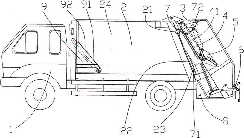
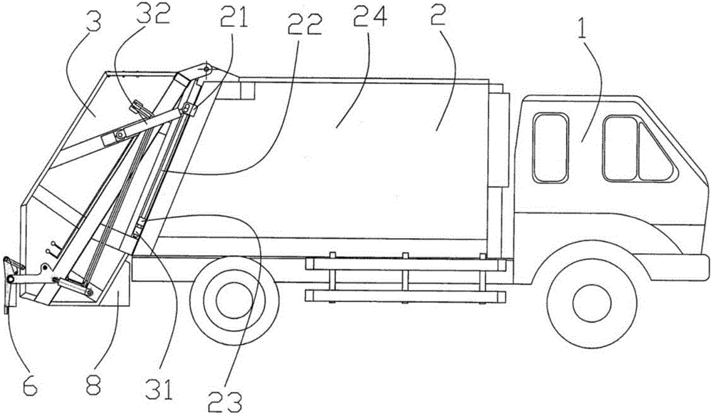
[0018] combine figure 1 with figure 2 , the compression protection device of the compression car, including the matching second-class automobile chassis 1 and the compression compartment 2, the rear compartment 3 is hinged on the loading end of the compression compartment 2, and the rear compartment 3 is equipped with a lifting plate assembly 4 and a scraper assembly 5 and the pail mechanism 6, a pushing mechanism 7 is also installed in the back compartment 3, and this pushing mechanism 7 is equipped with a pushing plate 71 that can be hinged with the upper front inner wall of the rear compartment 3, and the back side of the pushing plate 71 is rotatably connected with At least one push cylinder 72, the push cylinder 72 is rotatably connected to the top inner wall of the rear compartment 3 and is hinged. The push cylinder 72 is two arranged in parallel, and is gener...


PUM


Abstract

The invention discloses a compression protection device for a compression car, which comprises a matched second-class chassis of a car and a compression compartment. A rear compartment is hinged on the charging end of the compression compartment, and a lifting plate assembly is arranged inside the rear compartment. . The scraper assembly and the bucket lifting mechanism are characterized in that a pushing mechanism is installed in the rear compartment, and the pushing mechanism is equipped with a pushing plate that can be hinged to the upper front inner wall of the rear compartment, At least one pushing oil cylinder is rotatably connected to the back of the pushing plate, and the pushing oil cylinder is rotatably connected to the top inner wall of the rear compartment and is hinged. There are circular arc plates on both sides of the compression compartment, which has a compact structure, reduces the curb weight and improves the loading capacity of the vehicle; a sewage collection box is equipped to prevent sewage overflow during garbage treatment and effectively protect the surrounding environment; the upper part is set The pushing mechanism is improved, the compression ratio during garbage disposal is increased, the single garbage processing capacity of the whole vehicle is improved, and the appearance of the whole vehicle is enhanced at the same time.

Description

technical field [0001] The invention belongs to the technical field of garbage trucks in sanitation machinery, and in particular relates to a compression protection device for a compression truck. Background technique [0002] With the acceleration of the domestic urbanization process, how to improve the efficiency of garbage disposal has become the concern of all parties, especially a mobile garbage compactor. According to the current compressed garbage truck, most of them use built-in scraper extrusion. In this way, its operating range of garbage is limited to the layer-by-layer extrusion of garbage at the end. Relatively speaking, the pushing force is relatively small, and the garbage is still in a relatively loose state. In this way, under the same garbage storage volume, the garbage The actual loading capacity is limited, which reduces the amount of garbage to be processed at one time, and at the same time increases the cost of urban garbage treatment accordingly. The ...

Claims


Application Information

Patent Timeline
IPC IPC(8): B65F3/14
CPCB65F3/14B65F2003/006
Inventor 李金鸿赵新伟李洪宝
Owner QINGDAO ALLITE AUTO TECHNIC
Why Eureka
Try Eureka