Vertical fixed-point garbage compressor
A garbage compressor and garbage technology, which is applied in the direction of garbage transmission, garbage collection, loading/unloading, etc., can solve the problems of inconvenient production, installation, construction, transportation and maintenance, large volume of vertical compressors, hidden safety hazards of operators, etc. Achieve high pushing force, reasonable structure, and reduce equipment footprint
- Summary
- Abstract
- Description
- Claims
- Application Information
AI Technical Summary
Problems solved by technology
Method used
Image

Examples
Embodiment Construction
[0010] Below in conjunction with specific embodiment, preparation method of the present invention is described in further detail:
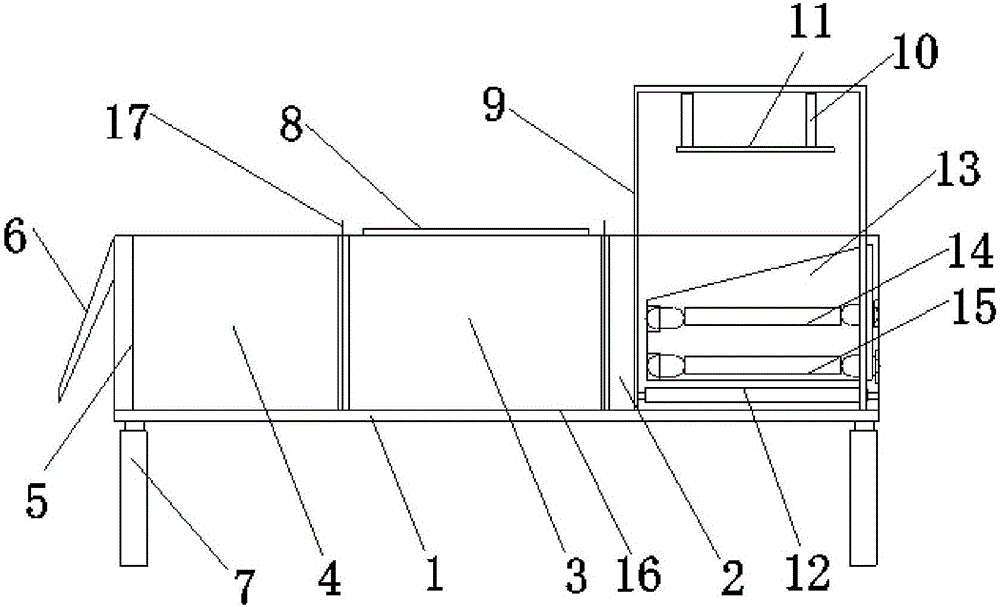
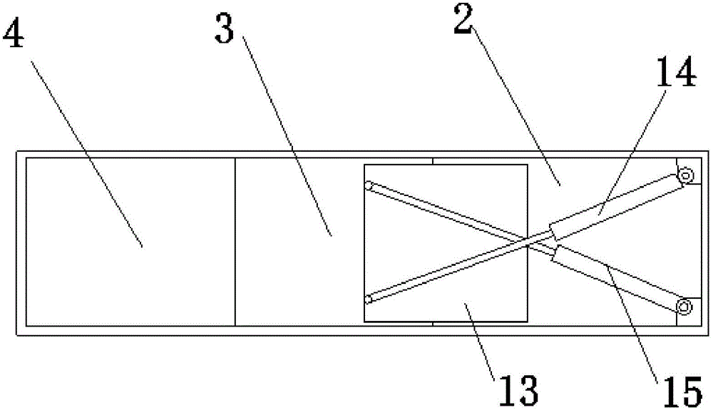
[0011] refer to figure 1 and figure 2 The shown vertical fixed-point garbage compressor includes a bracket 1, four hydraulic telescopic rods 7 are fixed on the bottom of the bracket 1, and a garbage box body is fixed above the bracket 1, and the garbage box body is sequentially divided from left to right It is a storage section 4 , a compression section 3 and an operation section 2 connected to each other, and the storage section 4 , the compression section 3 and the operation section 2 in the garbage bin are separated by an interposed partition 17 .
[0012] One side of the storage section 4 is provided with a garbage discharge port 5 and a flip baffle 6 is installed on the garbage discharge port 5; a garbage feed port 8 is provided above the compression section 3; A pushing mechanism is provided, and the pushing mechanism includes a first oil...
PUM
 Abstract
Description
Claims
Application Information