
Engine control method, system and vehicle

A control method and engine technology, applied in the direction of engine control, machine/engine, electrical control, etc., can solve the problems of unstable feedback control, weak ion current signal, difficult quantitative analysis, etc., to improve work uniformity and work performance. Effect

Active Publication Date: 2019-05-31
GREAT WALL MOTOR CO LTD
View PDF6 Cites 0 Cited by
  • Summary
  • Abstract
  • Description
  • Claims
  • Application Information

AI Technical Summary

Problems solved by technology

[0004] 1. Obtain the state of the cylinder indirectly by measuring the ionization current in the cylinder. Its characteristic is that the combustion signal is induced by the ion current signal, but it is difficult to analyze quantitatively. Moreover, the ion current signal is weak under light load conditions, which brings a lot to the feedback control. instability
[0005] 2. Through the instantaneous speed signal of the engine crankshaft, the working state of the cylinder is indirectly predicted. It is characterized by simple measurement and low cost, but it has great limitations, and cannot measure important parameters such as the average indicated pressure IMEP and the combustion midpoint CA50
[0007] The disadvantage of the prior art is that for the non-uniformity of the multi-cylinder engine, the fluctuation detection of the crankshaft instantaneous speed is mostly used, but this method has relatively large limitations, and cannot measure important parameters such as the average indicated pressure IMEP, the combustion midpoint CA50, etc. parameters; and there are still some methods that use ion current signals to induce combustion signals, which are difficult to quantitatively analyze, and under light load conditions, ion current signals are weak, which brings a lot of instability to feedback control

Method used


Image

  • Engine control method, system and vehicle
  • Engine control method, system and vehicle
  • Engine control method, system and vehicle

Examples


Embodiment Construction

[0049] It should be noted that, in the case of no conflict, the embodiments of the present invention and the features in the embodiments can be combined with each other.

[0050] The present invention will be described in detail below with reference to the accompanying drawings and examples.

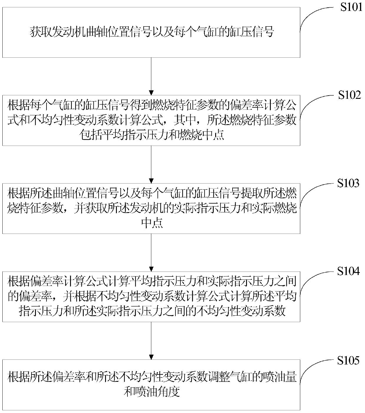
[0051] figure 1 is a flowchart of an engine control method according to an embodiment of the present invention.

[0052] Such as figure 1 As shown, the control method of the engine according to one embodiment of the present invention includes the following steps:

[0053] S101: Obtain a crankshaft position signal of the engine and a cylinder pressure signal of each cylinder. For example: through the cylinder pressure sensor, crankshaft position sensor, camshaft position sensor, etc. to detect the cylinder pressure signal, crankshaft position signal and camshaft position signal of each cylinder.

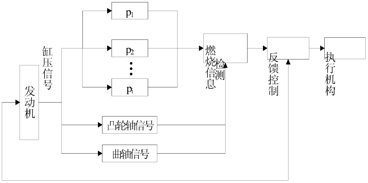
[0054] Specifically, as figure 2 As shown, the cylinder pressure signal of each cylind...


PUM


Abstract

The invention provides a control method of an engine, a system and a vehicle. The control method comprises the steps: a deviation ratio computational formula and a nonuniformity variation coefficient computational formula of a combustion characteristic parameter are acquired according to a cylinder pressure signal of each air cylinder; the combustion characteristic parameters are extracted, and practical indicated pressure and a practical combustion middle point of the engine are acquired; a deviation ratio and a nonuniformity variation coefficient between mean indicated pressure and the practical indicated pressure are calculated according to the deviation ratio computational formula and the nonuniformity variation coefficient computational formula; and the fuel-injection quantity and the fuel-injection angle of each air cylinder are adjusted according to the deviation ratio and the nonuniformity variation coefficient. With the adoption of the control method, the working uniformity of various cylinders of the engine can be improved, and the working performance of the engine can be further improved.

Description

technical field [0001] The invention relates to the technical field of automobiles, in particular to an engine control method, system and vehicle. Background technique [0002] The huge potential of Homogeneous Charge Compression Ignition (HCCI) and Premixed Charge Compression Ignition (PCCI) in terms of energy saving and emission reduction has attracted widespread attention. The above-mentioned combustion method relies on the chemical kinetic reaction of the combustible mixture in the cylinder to control the ignition time. One of the main technical difficulties is that it is much more difficult to control the ignition time than the traditional gasoline engine through the ignition time and the traditional diesel engine through the fuel injection time. It is difficult to find An effective control technology ensures that the combustion is carried out within a controllable degree, so that the combustion between the cylinders is inconsistent, and due to different friction losses...

Claims


Application Information

Patent Timeline
Patent Type & Authority Patents(China)
IPC IPC(8): F02D41/04
Inventor 于书海宋东先辛成林孙剑
Owner GREAT WALL MOTOR CO LTD
Learn More