stove burner

A technology for burners and stoves, which is applied to burners, gas fuel burners, combustion types, etc., can solve the problems of easy flame overflowing from the bottom of the pot, increased cost, and large heat loss, and achieves increased residence time and contact area. Processing and material costs, the effect of reducing the contaminated area

Active Publication Date: 2018-10-02
NINGBO FOTILE KITCHEN WARE CO LTD
View PDF9 Cites 0 Cited by
  • Summary
  • Abstract
  • Description
  • Claims
  • Application Information

AI Technical Summary

Problems solved by technology

Although the above-mentioned improved outer ring flame cover structure has a certain flame-stabilizing effect, the secondary air of the outer ring flame hole of the outer ring flame cover cannot be well supplemented, and its flame-stabilizing effect needs further improvement. improve
[0003] In addition, the existing cooker burners all have the following problems: 1. After the inner ring fire and the outer ring fire are designed separately, the flame-stabilizing structure of the inner ring fire cover and the flame-stabilizing structure of the outer ring fire cover need to be designed respectively, so that the entire combustion The structure of the device is relatively complicated, the cost is increased, and the flame stabilization effect is not ideal. The flame stabilization hole is easy to block. Once the flame stabilization hole is blocked, it is easy to cause fire failure, ignition failure, and thermocouple difficult to maintain and flameout phenomenon.
2. Due to the problem of inner and outer ring fires, in order to fully burn the inner ring fire, it is necessary to design a secondary air inlet to supplement the inner ring fire. At present, the burners on the market mainly use two ways to replenish from the chassis and from the top of the panel. Solve the problem of secondary air intake. For the burner that supplements the secondary air from the chassis, the existence of the secondary air intake will easily cause the overflow to flow into the chassis. For the burner that supplements the secondary air from the top of the panel, it will cause secondary The air inlet is not easy to clean
3. The design structure of the inner and outer ring fires requires enough secondary air inlets, so the diameter of the burner cannot be made small, generally above 100mm. In this way, the flame is easy to overflow the bottom of the pot during actual use, making the contact time between the high-temperature flue gas and the bottom of the pot And the area is reduced, the heat loss is large, and the thermal efficiency is low

Method used


Image

  • stove burner
  • stove burner
  • stove burner

Examples


Embodiment Construction

[0034] The present invention will be further described in detail below in conjunction with the accompanying drawings and embodiments.

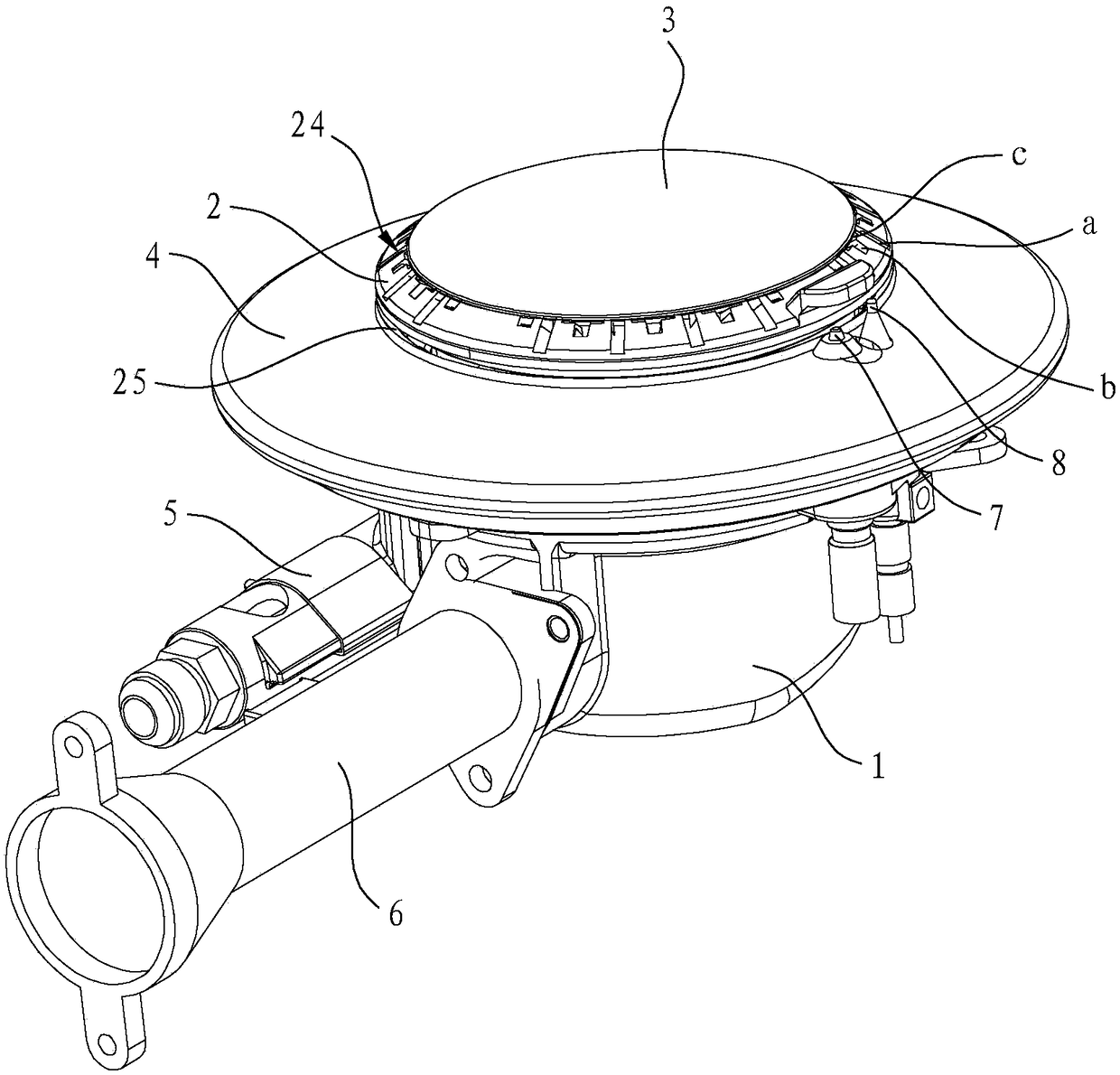
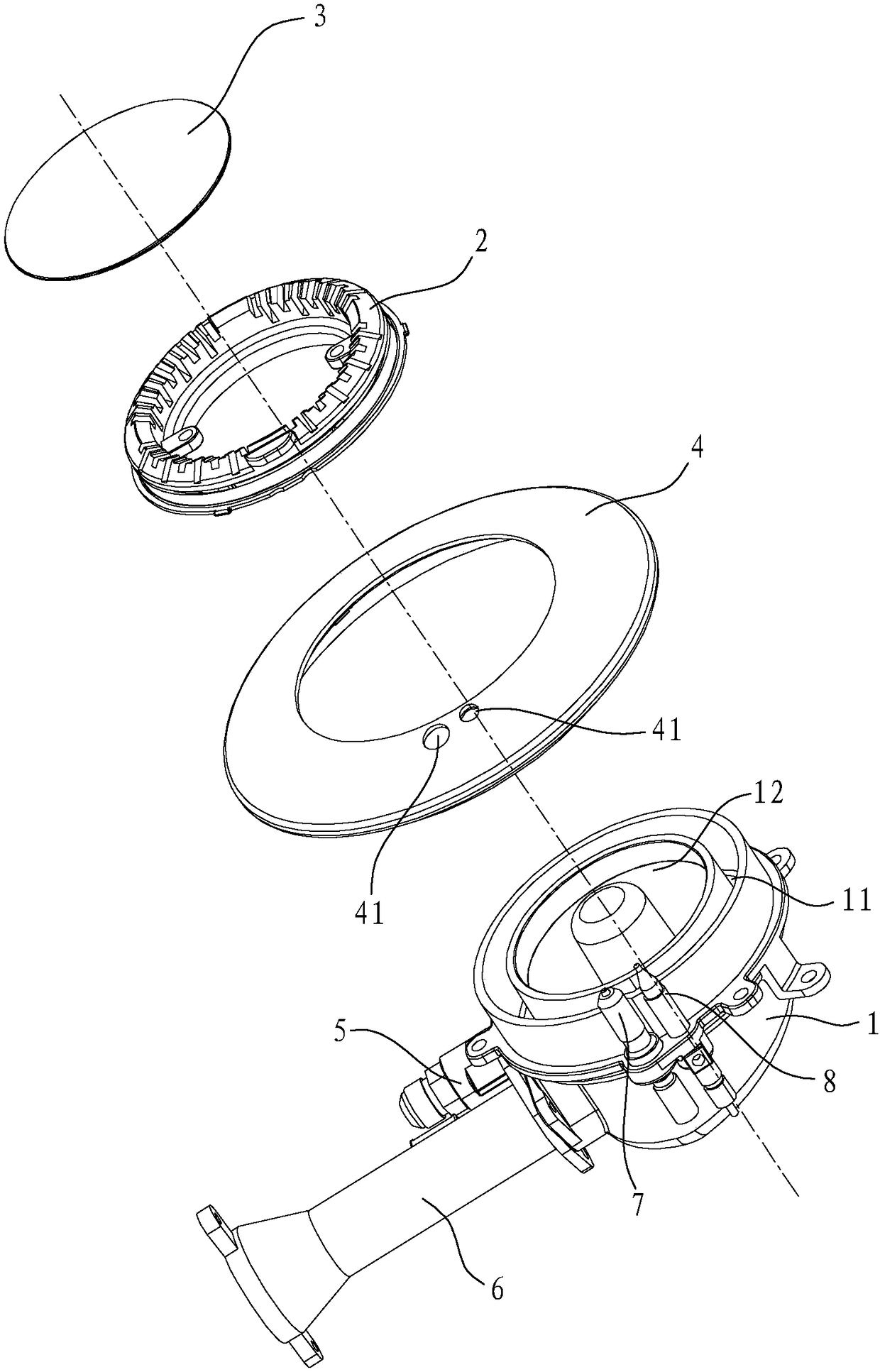
[0035] Such as figure 1 and figure 2 As shown, the stove burner in this embodiment includes a burner head 1, a fire cover 2, a cover plate 3, a decorative ring 4, an outer ring gas injection tube 5, an inner ring gas injection tube 6, an ignition needle 7 and a thermocouple 8 and other components.

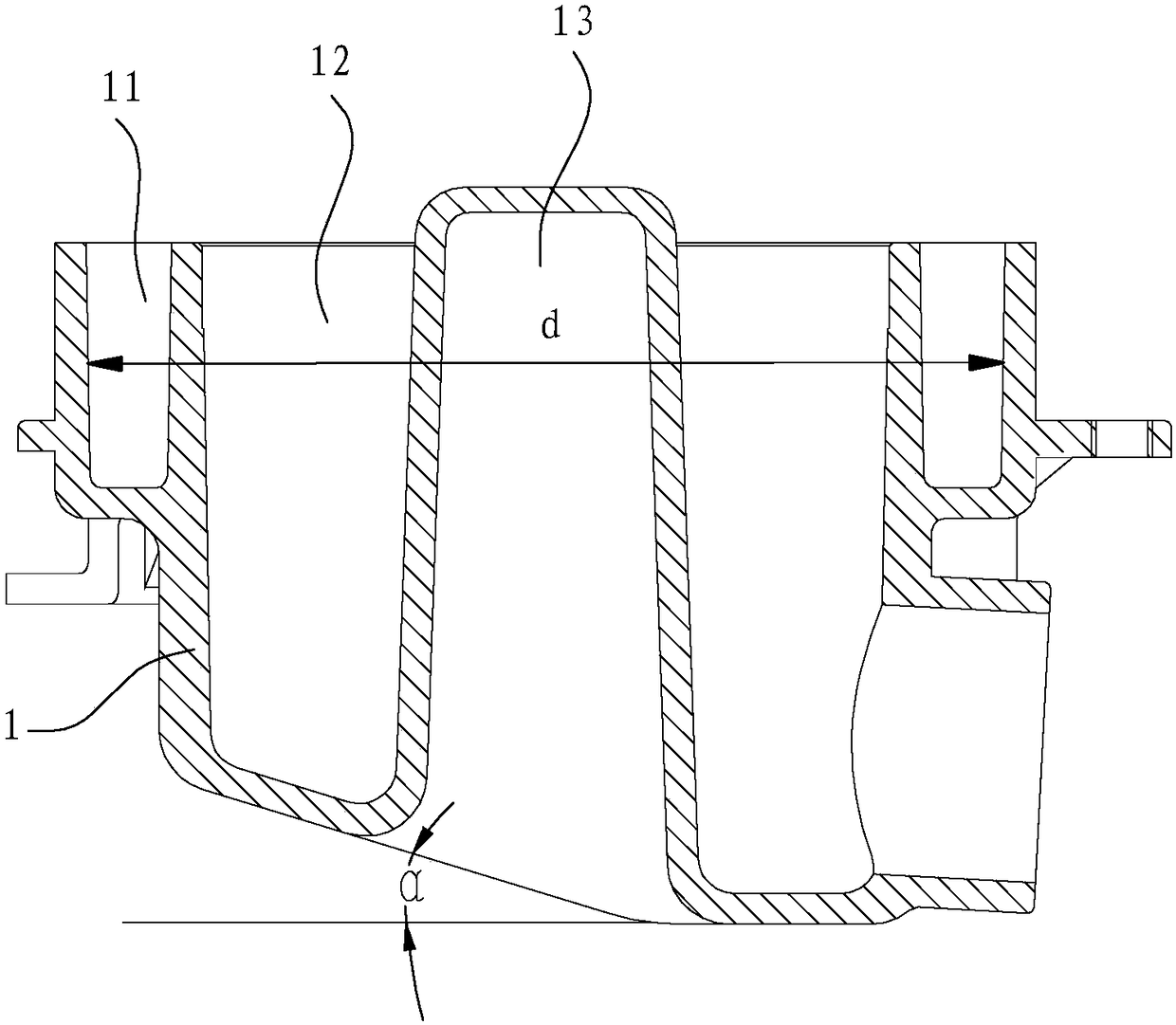
[0036] Such as image 3 As shown, the burner head 1 has an outer ring cavity 11, an inner ring cavity 12 and a cylindrical cavity 13, the cylindrical cavity 13 is concave upward from the bottom of the burner head 1, and the cylindrical cavity 13 is located inside The center of the ring cavity 12. The cylindrical cavity 13 acts as a flow guide, so that the uniformity of the airflow in the burner 1 is better, and the gas mixing effect is better. In addition, a temperature sensor can also be installed in the cylindrical cavity 13 to detect the f...


PUM


Abstract

A stove burner comprises a furnace head, an outer-ring gas ejector pipe, an inner-ring gas ejector pipe and a burner cap, wherein first main flame slots and second main flame slots which are radially distributed are formed in the upper surface of the burner cap along the circumferential direction, and arranged in a spacing manner; meanwhile, the slotting depth of each first main flame slot is greater than that of each second main flame slot; the length of each first main flame slot is greater than that of each second main flame slot; an upper-ring flame channel is formed between the peripheral part of a cover plate as well as the first main flame slots and the second main flame slots, and communicates with an inner-ring cavity; and a lower-ring flame channel positioned below the upper-ring flame channel is also formed in the burner cap, and communicates with the outer-ring cavity. After the stove burner provided by the invention adopts the upper-ring and lower-ring flame design, both the slight flaming effect and the flame stabilizing effect of lower-ring flame can be achieved; as the first main flame slots and the second main flame slots are arranged in a spacing manner, the secondary air supplementing effect is better; and in addition, the diameter of the stove burner is relatively small, so that is not only the heat efficiency improved, but also the stove burner is easier to clean.

Description

technical field [0001] The invention relates to a burner, in particular to a cooker burner. Background technique [0002] Existing cooker burners generally include a burner and an inner ring fire cover and an outer ring fire cover installed on the burner. and outer ring fire. At present, various outer ring fire cover structures with flame stabilizing functions have been disclosed in the prior art, such as "A Kind of Fuel Gas" disclosed in the Chinese utility model patent No. ZL200920112857.7 (authorized announcement No. Stove outer ring fire cover", the outer ring fire cover is provided with flame stabilizing holes on the outer surface, the flame stabilizing holes are located below the outer ring fire holes and arranged alternately with the outer ring fire holes, the inner end of the flame stabilizing holes and the gas channel of the fire cover The combustion efficiency is greatly improved due to the setting of the flame stabilizing hole, which can reduce the emission of c...

Claims


Application Information

Patent Timeline
Patent Type & Authority Patents(China)
IPC IPC(8): F23D14/02F23D14/26F23D14/46
CPCF23D14/02F23D14/26F23D14/46
Inventor 章建锋徐强茅忠群诸永定蔡国汉郑军妹
Owner NINGBO FOTILE KITCHEN WARE CO LTD
Why Eureka
Try Eureka