Eureka AIR delivers breakthrough ideas for toughest innovation challenges, trusted by R&D personnel around the world.

Large triggering delay quantization measuring method for laser vibration measurement calibration

A technology of trigger delay and laser vibration measurement, which is applied to measuring devices, using wave/particle radiation, and measuring ultrasonic/sonic/infrasonic waves, etc. It can solve the problems that the accuracy is not easy to be high, and the delay cannot be set arbitrarily.

Active Publication Date: 2016-11-23
BEIJING CHANGCHENG INST OF METROLOGY & MEASUREMENT AVIATION IND CORP OF CHINA
View PDF9 Cites 6 Cited by
  • Summary
  • Abstract
  • Description
  • Claims
  • Application Information

AI Technical Summary

Problems solved by technology

[0009] The purpose of the present invention is to overcome the shortcomings of the existing trigger delay measurement method, aiming at the current technical situation that the measurement calibration of the digital oscilloscope trigger with a large delay requires a high-precision large delay device and the delay cannot be set arbitrarily and the accuracy is not easy to be high. A Quantization Measurement Method of Large Trigger Delay for Laser Vibrometer Calibration

Method used


Image

  • Large triggering delay quantization measuring method for laser vibration measurement calibration
  • Large triggering delay quantization measuring method for laser vibration measurement calibration
  • Large triggering delay quantization measuring method for laser vibration measurement calibration

Examples


Embodiment 1

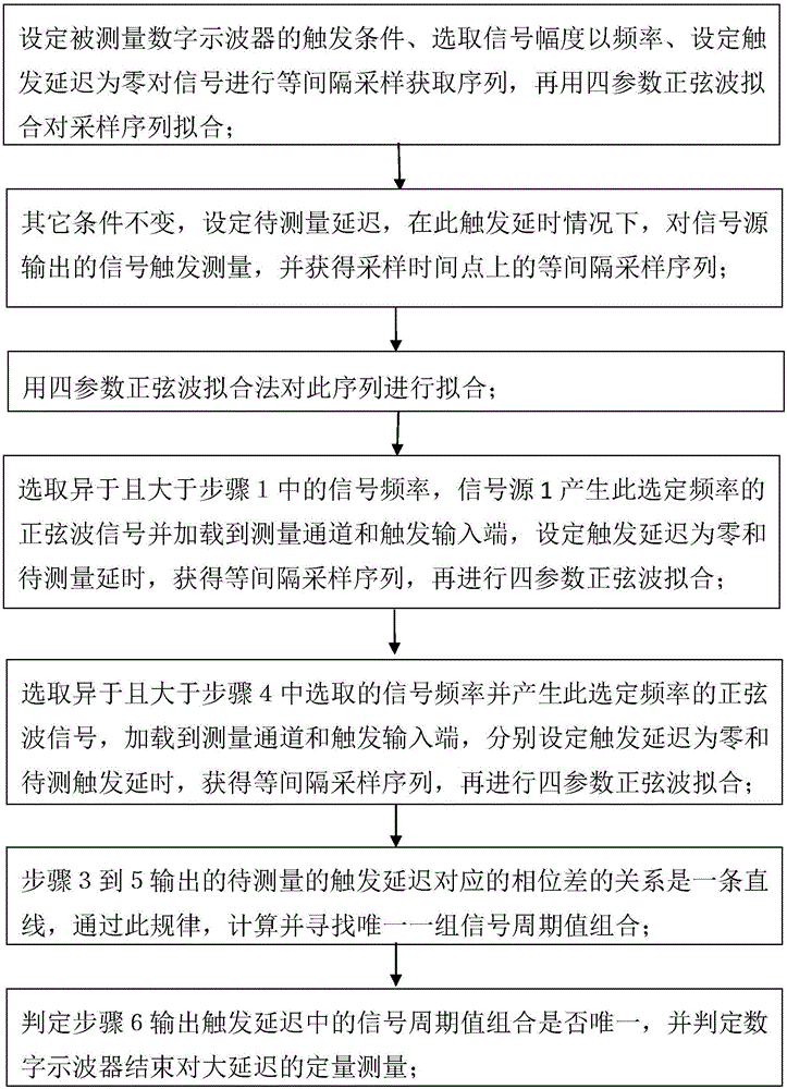
[0094] A quantization measurement method with large trigger delay for laser vibrometer calibration, the flow chart of which is as follows figure 1 shown.

[0095] Depend on figure 1 As can be seen, the method of the present invention comprises the following steps:

[0096] Step 1: Set the trigger condition of the digital oscilloscope to be measured, select the signal amplitude and frequency, set the trigger delay to zero, sample the signal at equal intervals to obtain the sequence, and then use the four-parameter sine wave fitting to fit the sampling sequence;

[0097] Step 2: Other conditions remain the same, set the delay to be measured, in the case of this trigger delay, trigger the measurement of the signal output by the signal source, and obtain the equally spaced sampling sequence at the sampling time point;

[0098] Step 3: Carry out least square waveform fitting with the four-parameter sine wave fitting method;

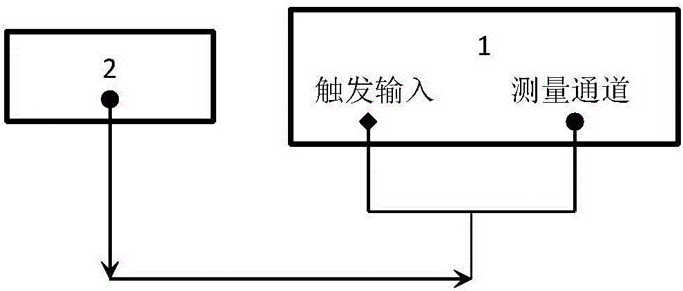
[0099] Step 4: Select a signal frequency that is diff...

Embodiment 2

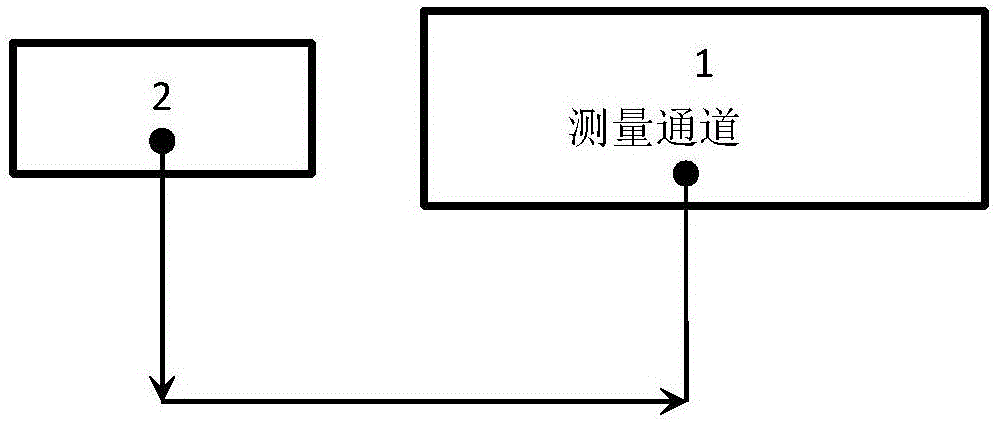
[0117] A quantized measurement method with large trigger delay for laser vibrometer calibration, such as image 3 As shown, 1 is a digital oscilloscope, and 2 is a sinusoidal signal source, through which a sinusoidal excitation is applied to the measured digital oscilloscope 1, and a sinusoidal trigger signal is provided to it at the same time. The specific process is the same as that of Embodiment 1, except that the trigger channel is the input channel itself, and there is no need to introduce it from a special trigger terminal.


PUM


Abstract

The invention relates to a large triggering delay quantization measuring method for laser vibration measurement calibration, and belongs to the technical field of wireless measurement testing. The characteristics that the phase difference and the frequency of sine signals corresponding to the same delay time difference are in direct proportion and the phase has the periodic quantization characteristic at the same time are utilized, three different frequency sine waveforms in mutual prime number rules are used as triggering excitation signals, the characteristics that the phase difference phik of fixed triggering delay tau under different frequencies fk has the quantization characteristic of jumping at 2pi intervals on the basis of a basic phase difference and theoretically different frequency points (fk, phik) are on the same straight line are used for judging a quantization integer, tau is measured with the sine excitation signal cycle (frequencies fk) and the phase difference phik, and the delay of a laser vibration measurement instrument can be further read through the large triggering delay measurement function of a digital oscilloscope. According to the large triggering delay quantization measuring method for laser vibration measurement calibration, no hardware delay devices are needed, and any selected large triggering delay can be accurately measured and calibrated.

Description

technical field [0001] The invention relates to a quantization measurement method with a large trigger delay for laser vibration measurement and calibration, and belongs to the technical field of radio measurement and testing. Background technique [0002] For the vibration measurement problem in vibration measurement and calibration, since the signal waveform comes from the sine wave of the electrical signal source, the final output is the sinusoidal vibration waveform output by the vibration table. After passing through electromechanical links such as power amplifiers and mechanical vibration tables, the sinusoidal vibration waveform has a relatively large time delay compared with the sinusoidal waveform in the electrical signal source. If the time delay is greater than one sinusoidal waveform period, it is generally considered to be a large delay. , can not be solved by the direct phase measurement method, and can only be measured and calibrated by a special trigger delay...

Claims


Application Information

Patent Timeline
IPC IPC(8): G01H9/00
CPCG01H9/00
Inventor 梁志国朱振宇
Owner BEIJING CHANGCHENG INST OF METROLOGY & MEASUREMENT AVIATION IND CORP OF CHINA
Why Eureka
Eureka Blog
Learn More