Compact type millimeter-wave monopulse antenna

A monopulse and millimeter wave technology, which is applied to antennas, antenna arrays, antenna supports/mounting devices, etc., can solve the problems of monopulse antennas that are bulky, difficult to integrate high-frequency components, and bulky, and achieve light weight , Low processing cost, small size effect

Inactive Publication Date: 2016-11-23
UNIV OF ELECTRONICS SCI & TECH OF CHINA
View PDF5 Cites 11 Cited by
  • Summary
  • Abstract
  • Description
  • Claims
  • Application Information

AI Technical Summary

Problems solved by technology

[0006] The purpose of the present invention is to overcome the shortcomings of traditional monopulse antennas such as bulky body, bulky size, and difficulty in connecting with other integrated high-frequency components, and propose a compact millimeter-wave monopulse antenna

Method used


Image

  • Compact type millimeter-wave monopulse antenna
  • Compact type millimeter-wave monopulse antenna
  • Compact type millimeter-wave monopulse antenna

Examples


Embodiment Construction

[0034] In order to better illustrate the purpose and advantages of the present invention, the content of the present invention will be further described below in conjunction with the accompanying drawings and specific embodiments.

[0035] In the present invention, the content of the present invention is specifically described by taking a compact monopulse antenna in the Ka band, with a main reflection surface diameter of 170 mm and a secondary reflection surface diameter of 48 mm as an example.

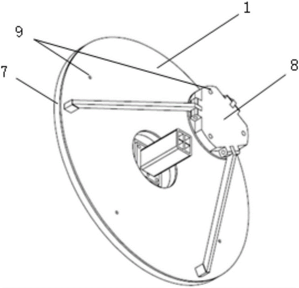
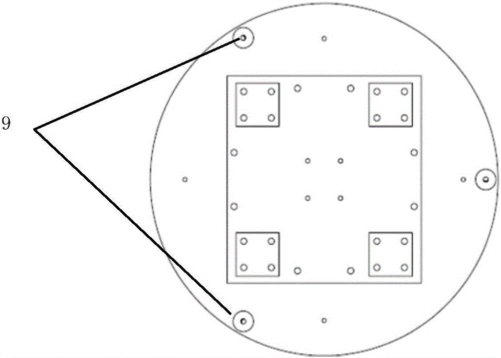
[0036] see figure 1 , figure 2 as well as image 3 , The compact monopulse antenna of this embodiment is composed of a main reflector 1 , a supporting structure, a secondary reflector 3 , a feed source 4 , and a sum and difference network 5 . The support structure includes a sum and difference network substrate 6, a main reflector substrate 7, a secondary reflector substrate 8, and three support rods 2 fixedly connecting them.

[0037] The main reflector 1 is fixed on the main re...


PUM


Abstract

The invention discloses a compact type millimeter-wave monopulse antenna and belongs to the technical field of antennas. The compact-type millimeter-wave mmonopulse antenna comprises a feed source, a main reflecting surface, an auxiliary reflecting surface, a supporting structure and a sum-difference network. Both the main reflecting surface and the auxiliary reflecting surface adopt plane reflection array antennas, and the sum-difference network is of a plane structure. Compared with a traditional monopulse antenna, the compact type millimeter-wave monopulse antenna has the advantages of small size, light weight and proneness to connection with other integrated high-frequency components.

Description

technical field [0001] The invention belongs to the technical field of antennas, and in particular relates to a compact millimeter-wave monopulse antenna, which can be used to reduce the volume and quality of traditional monopulse antennas and improve the integration of monopulse antennas and systems. Background technique [0002] Millimeter wave belongs to the wavelength range where microwave and far-infrared waves overlap. It has three characteristics: unique atmospheric transmission characteristics, available frequency bandwidth and short millimeter wave wavelength. The unique atmospheric transmission characteristics make the attenuation of the millimeter-wave antenna small when propagating through the atmospheric window, and are less affected by natural light and heat radiation sources; the available frequency bandwidth is beneficial to the millimeter-wave antenna to reduce multipath effects and suppress clutter effects, and enhance the anti-interference ability of the sy...

Claims


Application Information

Patent Timeline
Patent Type & Authority Applications(China)
IPC IPC(8): H01Q21/00H01Q1/12H01Q13/02H01Q15/14
CPCH01Q21/00H01Q1/12H01Q13/02H01Q15/14
Inventor 李浩赵加宁李天明
Owner UNIV OF ELECTRONICS SCI & TECH OF CHINA
Why Eureka
Try Eureka