High-voltage distribution cabinet of electric vehicle

A technology for high-voltage power distribution and electric vehicles, which is applied in substation/power distribution device shells, electrical components, panel/switch station circuit devices, etc., and can solve the problem of low protection level of high-voltage boxes, imperfect protection measures, and incomplete circuit monitoring systems and other problems, to improve the waterproof performance, prevent the circuit from overheating and burn out the resistors and components, and achieve the effect of overall beauty

Inactive Publication Date: 2016-11-23
湖南长高电气有限公司
7 Cites 1 Cited by

AI-Extracted Technical Summary

Problems solved by technology

[0003] The function of the high-voltage distribution box is to distribute the electric energy transmitted by the battery pack to various electrical equipment. However, most of the high-voltage distribu...

Method used

Case cover 200 of the present invention is provided with installation groove 204, can be used for installing nameplate, the nameplate installation groove of case cover 200 can make the nameplate of each case cover 200 stick on the corresponding position of corresponding case cover 200, make finished product The overall high-voltage distribution box is beautiful and tidy.
Specifically, the present invention includes casing 100, casting box cover 200, and casing 100 is provided with battery positive connector 101, battery negative connector 102, electric defrosting connector 103, vehicle-mounted charging connector 104, insulation Detect connector 105, air conditioner connector 106, DC-DC connector 107, low voltage control waterproof connector 108, motor positive connector 109, motor negative connector 110. Using connectors to transmit the power distributed in the high-voltage distribution box to each electrical equipment not only improves the protection level of the box, but also plays a very good role in foolproofing. Among them, preferably, both the box body 100 and the box cover 200 of the present invention are castings, which can enhance waterproof performance and overall stability.
The casing 100 of electric vehicle high-voltage distribution box of the present invention is provided with boss 121, and boss 121 is waterproof setting, and boss 121 matches with the groove 201 of box cover 200, has further improved hig...

Abstract

The invention discloses a high-voltage distribution cabinet of an electric vehicle. The cabinet comprises a cabinet body and a cabinet cover. A concave cavity is formed in the cabinet body and internally provided with a circuit board, a current detector, a fuse, thermistors, a relay, a copper bar and a wire. A plurality of electrically connected connectors are arranged on the outer wall of the cabinet body, a boss is circumferentially arranged on the end face of an opening of the concave cavity of the cabinet body, the cabinet cover is provided with a groove matched with the boss in a clamped mode, and a rubber ring is disposed in the groove. By means of the connectors, electricity allocated into the high-voltage distribution cabinet is transmitted to various electric appliances, the protection grade of the cabinet body can be improved, and a good fool-proof function can be achieved. The positive temperature thermistor and the negative temperature thermistor can effectively prevent the situation that a circuit is too hot and accordingly resistors and elements are burnt, and the safety coefficient of equipment is improved.

Application Domain

Technology Topic

Image

  • High-voltage distribution cabinet of electric vehicle
  • High-voltage distribution cabinet of electric vehicle
  • High-voltage distribution cabinet of electric vehicle

Examples

  • Experimental program(1)

Example Embodiment

[0032] Example one
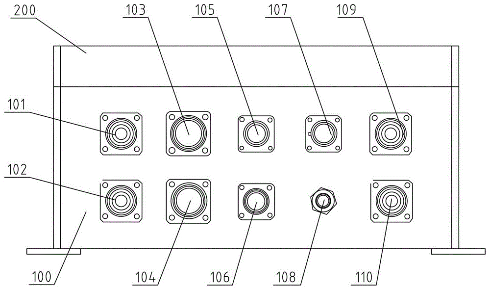
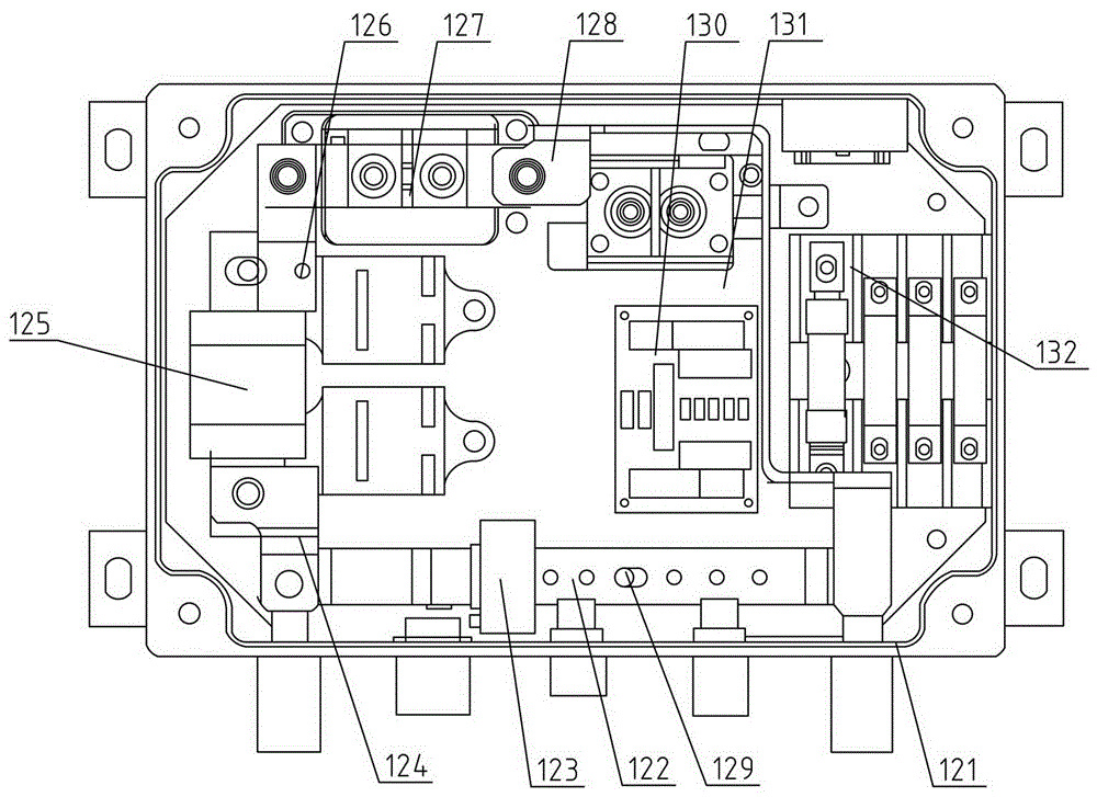
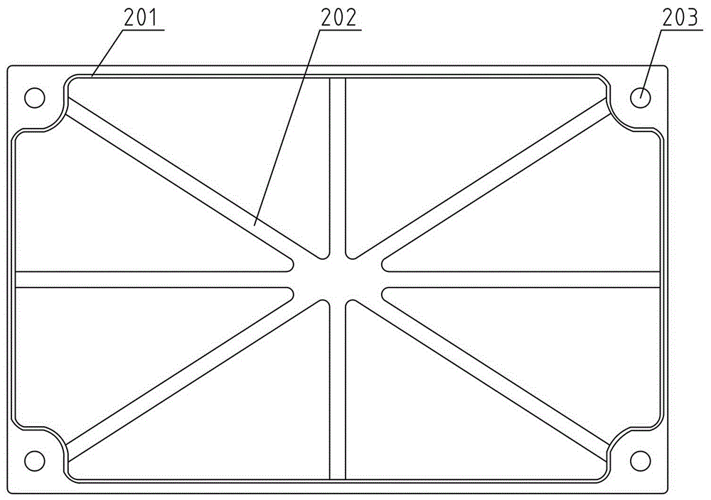
[0033] Such as Figure 1 to Figure 4 As shown, a high-voltage power distribution box for an electric vehicle of the present invention includes a box body and a box cover, the box body is provided with a concave cavity, and a circuit board, a current detector, and a fuse are installed in the concave cavity of the box body , Thermistors, relays, copper bars, wires, the outer wall of the box is provided with a plurality of electrical connectors, the open end surface of the concave cavity of the box is provided with a boss in the circumferential direction, the box The cover is provided with a groove for engaging with the boss, and a rubber ring is arranged in the groove of the box cover.
[0034] Specifically, the present invention includes a box body 100, a casting box cover 200, and the box body 100 is provided with a battery positive connector 101, a battery negative connector 102, an electric defrosting connector 103, a vehicle charging connector 104, and an insulation detection connector 105. Air conditioner connector 106, DC-DC connector 107, low voltage control waterproof connector 108, motor positive connector 109, motor negative connector 110. The use of connectors to transmit the electricity distributed in the high-voltage distribution box to the electrical equipment not only improves the protection level of the box, but also plays a good role in preventing fools. Among them, preferably, the box body 100 and the box cover 200 of the present invention are both castings, which can enhance waterproof performance and overall stability.
[0035] The box body 100 of the electric vehicle high-voltage power distribution box of the present invention is provided with a boss 121. The boss 121 is a waterproof setting. The boss 121 is matched with the groove 201 of the box cover 200 to further improve the protection level of the high-voltage power distribution box. .
[0036] The circuit board 130 integrates two thermistors and all surge diodes. The precharge resistor of the present invention uses a positive temperature coefficient thermistor to replace the traditional resistor has the following advantages: When the load fails due to a short circuit, the precharge voltage is always at On the pre-charging resistor, the current is too large at this time. If the pre-charging circuit is an ordinary resistor, it may eventually cause the resistor to burn out due to excessive heat in the circuit. Use a positive temperature coefficient thermistor when the circuit heats up too much. The resistance of the sensitive resistor will present a high resistance state to suppress the current value, thereby protecting the equipment.
[0037] The DC-DC circuit of the present invention is also connected in series with a negative temperature coefficient thermistor. The negative temperature coefficient thermistor plays a role in precharging the capacitive load DC-DC. The precharging process is: when the DC-DC circuit is energized , The temperature is lower, the resistance of the negative temperature coefficient thermistor is higher, and the DC-DC starting current is small; when the power is turned on for a period of time, the temperature of the negative temperature coefficient thermistor increases and the resistance decreases until the resistance value is negligible , So as to complete the pre-charge of the circuit.
[0038] The box of the present invention is provided with a Hall current detector 123 installed on the negative copper bar 122, the negative copper bar is installed on the battery negative connector, the motor controller negative connector and the insulating column 129 with screws, and the main fuse 125 One end is connected to the battery positive connector through the copper bar 124, one end is connected to the main positive relay 127 through the copper bar 126, the other end of the main positive relay 127 is connected to the electrical control positive connector through the copper bar 128, and the circuit board 130 is installed on the bottom plate through copper support On 131, the fuses of the remaining circuits are all installed on the fuse mounting plate 132, the fuse mounting plate is mounted on the bottom plate 131 with screws, and the remaining circuit connections are connected with wires for electric vehicles.
[0039] The box cover of the present invention is provided with a groove 201, and the groove 201 on the box cover is matched with the anti-convex platform 121 of the box body, which facilitates the waterproof installation. The box cover 200 is provided with reinforcing ribs 202 to enhance the structural strength of the box 200. The box cover 200 is provided with four through holes. The through holes are the installation through holes 203. The installation through holes of the box cover 200 are provided for screw sealing. Box body box cover, the box body is provided with matching mounting holes.
[0040] The box cover 200 of the present invention is provided with an installation slot 204, which can be used to install nameplates. The nameplate installation slot of the box cover 200 can make the nameplate of each box cover 200 stick to the corresponding position of the corresponding box cover 200, so that the finished product is high-voltage power distribution The whole box is beautiful and neat.

PUM

no PUM

Description & Claims & Application Information

We can also present the details of the Description, Claims and Application information to help users get a comprehensive understanding of the technical details of the patent, such as background art, summary of invention, brief description of drawings, description of embodiments, and other original content. On the other hand, users can also determine the specific scope of protection of the technology through the list of claims; as well as understand the changes in the life cycle of the technology with the presentation of the patent timeline. Login to view more.

Similar technology patents

Fireproof bus groove

Owner:JIANGSU HUAPENG INTELLIGENT ELECTRICAL

Safety enhanced automobile safety belt fixing device

InactiveCN106114446AIncreased security levelHigh protection levelBelt anchoring devicesMusic playerCushion
Owner:KUNSHAN HAOSHUO PRECISION MECHANISM CO LTD

DC motor

InactiveCN104218760AEasy to test and debugHigh protection levelDC commutatorEngineeringNuclear power
Owner:XIAN TECH FULL SIMO MOTOR

Classification and recommendation of technical efficacy words

  • Good anti-fooling effect
  • High protection level

Virtual disk-based file protection system and method

ActiveCN102214283AHigh protection levelPrevent file leaksDigital data protectionOperating systemProtection system
Owner:厦门天锐科技股份有限公司

Protective motorcycle impact cage

InactiveUS7175200B1High protection levelReduce the likelihood of injuryPedestrian/occupant safety arrangementCycle safety equipmentsControl engineering
Owner:OBERSTIAN TRACY G
Why Eureka
Try Eureka