
Method for providing two-way optical timed channel on optical transport network (OTN)

A two-way communication, optical technology, applied in the field of wired communication, can solve the problems of synchronization performance degradation, fiber chromatic dispersion coefficient is not a unique value, network scale limitation, etc., to improve time distribution performance, achieve link symmetry, and reduce operating costs Effect

Inactive Publication Date: 2016-11-23
ALCATEL LUCENT SAS
View PDF10 Cites 4 Cited by
  • Summary
  • Abstract
  • Description
  • Claims
  • Application Information

AI Technical Summary

Problems solved by technology

[0005] But there are two sources affecting the end-to-end (End-to-End) PTP performance in the OTN network
The first source is the link asymmetry between the master and slave clocks, which, if not measured and compensated for, can easily lead to timing errors with half the value of the link asymmetry
However, link asymmetry is common in OTN and not easily measured
The second source is when time nodes are cascaded along the timing path, the synchronization performance will be degraded or the network size will be limited due to the accumulated noise
[0014] Solution A has the following disadvantages: OSC needs to be terminated and processed at each node, and each node also terminates the timing signal and acts as a timing node
[0016] Option B has the disadvantage that for system and network management, the OSC needs to be terminated and processed on each node, which also terminates the timing signal and acts as a timing node
Obviously, there is a problem of accuracy in this method, because the chromatic dispersion coefficient of the optical fiber is not a unique value, and the OSC wavelength in practical applications is not the central wavelength, OSC is a sparse wavelength division multiplexing (Coarse WavelengthDivision Multiplexing, CWDM) channel, which allows + / -7.5nm offset from center wavelength)

Method used


Image

  • Method for providing two-way optical timed channel on optical transport network (OTN)
  • Method for providing two-way optical timed channel on optical transport network (OTN)
  • Method for providing two-way optical timed channel on optical transport network (OTN)

Examples


Embodiment Construction

[0043] Preferred embodiments of the present disclosure will be described in more detail below with reference to the accompanying drawings. Although preferred embodiments of the present disclosure are shown in the drawings, it should be understood that the present disclosure may be embodied in various forms and should not be limited to the embodiments set forth herein. Rather, these embodiments are provided so that this disclosure will be thorough and complete, and will fully convey the scope of the disclosure to those skilled in the art.

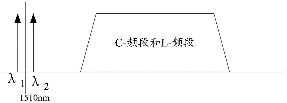
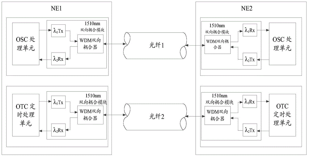
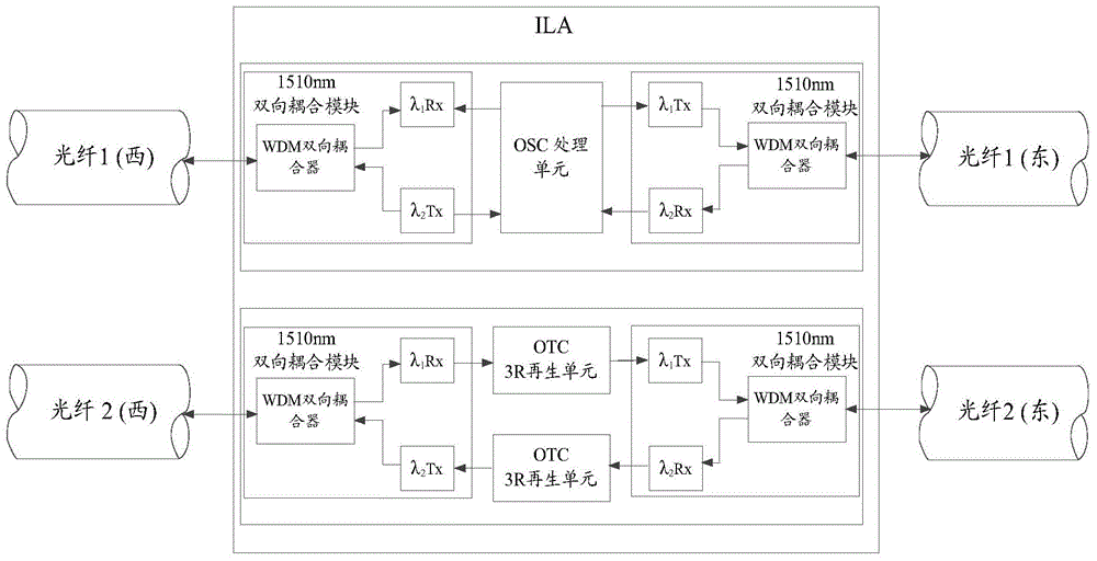
[0044] The present invention proposes a method for providing a bidirectional optical timing channel to realize timing distribution in OTN, including: configuring bidirectional communication channels respectively located on two optical fibers, configuring a first wavelength and a second wavelength on each optical fiber to Data is transmitted in two opposite directions, wherein the first wavelength and the second wavelength are DWDM wavelength...


PUM


Abstract

The invention provides a method for realizing timed distribution in an optical transport network (OTN). The method comprises the following steps of: on the basis of the wavelength of an optical supervisory channel (OSC) used in the OTN, configuring a two-way communication channel on an optical fibre, wherein optical signals having a first wavelength and a second wavelength respectively adjacent to the central wavelength of the OSC are configured on each optical fibre, so that data is transmitted in two directions; performing OSC duplex communication in a first two-way communication channel at the position of an optical switching / multiplexing node, and performing optical timed channel (OTC) duplex communication in a second two-way communication channel; and regenerating signals in the OTC through a line amplifier (ILA), so that timed signals in the OTC are transparently transmitted.

Description

technical field [0001] The present invention generally relates to the field of wired communication, and more specifically, relates to a method for providing a bidirectional optical timing channel on an Optical Transport Network (OTN) to simultaneously transmit frequency information and time information. Background technique [0002] Traditional network synchronization depends on the precise distribution of frequencies, and evolved wireless networks (eg, TD-LTE) require precise time and phase distributions. Currently, the IEEE1588V2 protocol (PTP) is commonly used to implement timing synchronization functions with sub-microsecond range precision. In order to simplify the network structure and reduce operation consumption, the primary reference clock (PRTC) is suggested to be arranged at the top of the OTN network. So time / phase is distributed over OTN from the main reference clock to the backhaul network. [0003] In order to realize precise time / phase transmission on the O...

Claims


Application Information

Patent Timeline
Patent Type & Authority Applications(China)
IPC IPC(8): H04Q11/00
Inventor 欧阳勇张欢
Owner ALCATEL LUCENT SAS
Learn More