
Oil pump controller and oil pump bracket assembly

A bracket assembly and controller technology, applied in the direction of pump control, machine/engine, arrangement of circuit components without support structure, etc., can solve the problems of increasing the cost of parts, difficult to arrange other parts, and occupying chassis space, etc., to achieve Ease of after-sales replacement, save space, and save wiring harness

Inactive Publication Date: 2016-11-23
UNITED AUTOMOTIVE ELECTRONICS SYST
View PDF7 Cites 2 Cited by
  • Summary
  • Abstract
  • Description
  • Claims
  • Application Information

AI Technical Summary

Problems solved by technology

This separate design requires a separate complete oil pump controller 2 housing and its fixed chassis bracket parts, and also requires a complex wiring harness 3 with multiple pins (pins) for connecting the oil pump controller 2 and the oil pump assembly. 1, not only takes up limited space on the chassis, but also increases the cost of parts
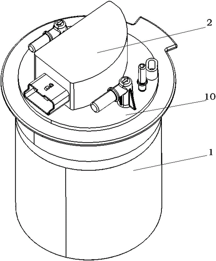
[0003] Flange integrated oil pump controller such as figure 2 As shown, the oil pump controller 2 is integrated on the flange 10 of the oil pump assembly 1, but it cannot be disassembled and replaced after sales, and the area of ​​the oil pump controller 2 occupies even more than 60% of the layout space of the flange 10, making it difficult to re-arrange. other parts
Because the oil pump controller 2 itself needs to adapt to the space arrangement on the flange 10, its body is usually designed as an irregular shape, such as an irregular sector, which leads to a sharp increase in the cutting cost and chip placement cost of the oil pump controller 2 circuit board.

Method used


Image

  • Oil pump controller and oil pump bracket assembly
  • Oil pump controller and oil pump bracket assembly
  • Oil pump controller and oil pump bracket assembly

Examples


Embodiment 1

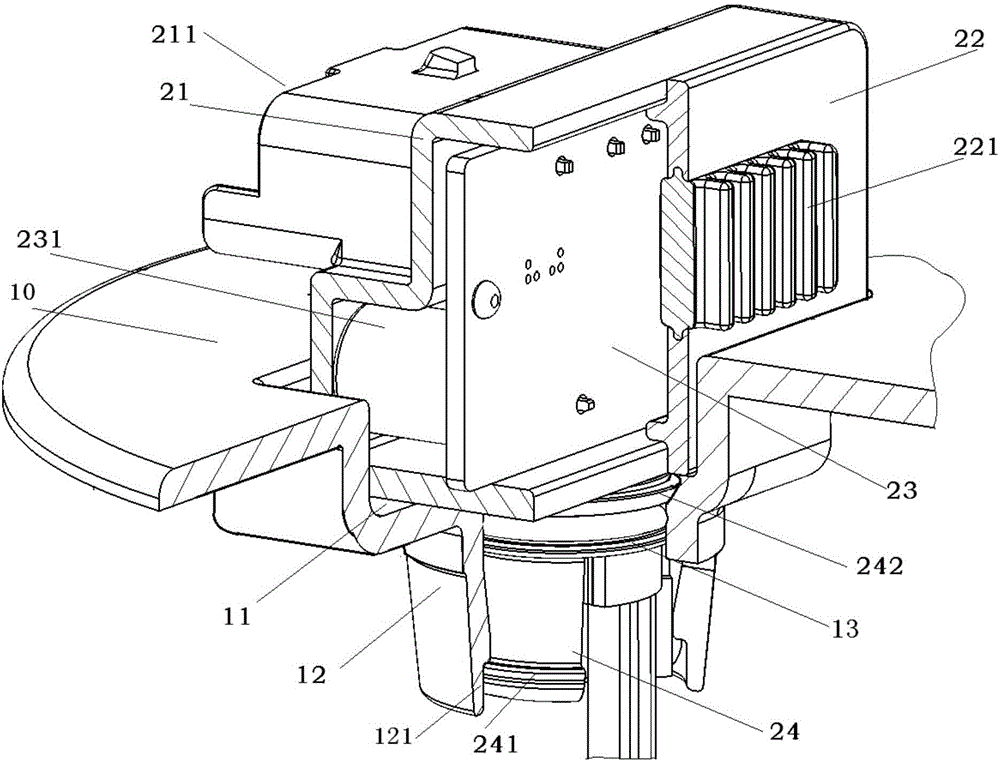
[0054] An oil pump bracket assembly, such as image 3 , Figure 4 , Figure 5 , Image 6 As shown, it includes an oil pump controller and a flange 10;

[0055] The oil pump controller includes a housing, a PCB (printed circuit board) 23, and a flange connector;

[0056] The outer wall of the housing is injection-molded and fixed with a pin (pin) 210;

[0057] The pin (pin) 210 has one end protruding from the outer wall of the housing to form a controller electrical plug 211;

[0058] The PCB board is vertically placed in the cavity of the housing;

[0059] The flange connector is arranged at the lower end of the bottom surface of the housing, and can be assembled and fixed with the flange;

[0060] The flange is provided with a groove, and the bottom of the groove is provided with a mounting hole 12, and the flange connector of the oil pump controller is clamped in the mounting hole.

[0061] Preferably, the oil pump controller is detachably connected to the flange.

[0...

Embodiment 2

[0066] Based on the oil pump bracket assembly of Embodiment 1, such as image 3 , Figure 4 As shown, the controller electric plug 211 of the oil pump controller is located on the side wall of the housing,

[0067] Capacitors and inductors are placed on the side of the PCB 23 close to the electrical plug 211 of the controller, and the capacitors and inductors are located below the pins 210 .

[0068] Preferably, the PCB board 23 includes two edges in the first direction and two edges in the second direction, the length of the edges in the first direction is not longer than the length of the edges in the second direction, and the PCB The plate 23 is placed in the cavity of the housing and one edge in the first direction is located at the upper end of the bottom surface of the housing.

[0069] Under normal circumstances, electronic components are arranged on the PCB board according to the electrical requirements. If the electric plug of the oil pump controller is arranged on ...

Embodiment 3

[0071] Based on the oil pump bracket assembly of Embodiment 1, such as image 3 As shown, the flange 10 is provided with a groove 11;

[0072] The bottom of the groove 11 communicates with a mounting hole 12;

[0073] The flange connector 24 provided at the lower end of the lower wall of the oil pump controller housing is tubular;

[0074] The lower end of the flange connector 24 is provided with a plurality of connector buckles 241 along the circumference.

[0075] The oil pump controller is fitted and assembled with the groove 11 of the flange 10 and the mounting hole 12 through the flange connector 24 .

[0076] In the oil pump bracket assembly of the third embodiment, the lower part of the oil pump controller can sink into the groove 11 and the installation pipe 12 on the flange 10, which reduces the characteristic height of the oil pump controller on the flange surface.


PUM


Abstract

The invention discloses an oil pump controller and an oil pump bracket assembly integrated with the oil pump controller. The oil pump controller comprises a shell, a PCB and a flange connecting head, wherein an insert needle is fixed on the outer wall of one surface of the shell in an injection molding manner, and one end of the insert needle stretches out of the outer wall of the shell to form a controller electric plug; the PCB is vertically placed in a cavity of the shell; the flange connecting head is arranged at the lower end of the bottom surface of the shell and can be fixedly matched and assembled with a flange; and the flange is provided with a groove, a mounting hole is formed in the bottom of the groove, and the flange connecting head of the oil pump controller is clamped into the mounting hole. The oil pump controller is small in size, a wiring harness and an electrical plug between the oil pump controller and an oil pump assembly can be saved, and after-sale replacement of the oil pump controller is facilitated.

Description

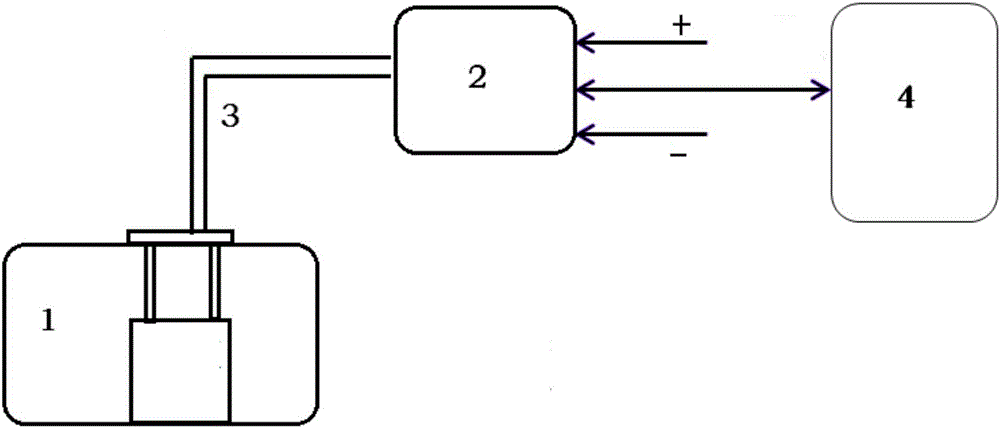
technical field [0001] The invention relates to an automobile oil supply device, in particular to an oil pump controller and an oil pump bracket assembly. Background technique [0002] In the current automotive fuel pump control system that supplies fuel on demand, the separate fuel pump controller such as figure 1 As shown, the oil pump controller 2 is a part independent of the oil pump assembly 1, the oil pump controller 2 communicates with the engine controller 4, and is separately installed on the fuel tank or somewhere on the chassis. This separate design requires a separate complete oil pump controller 2 housing and its fixed chassis bracket parts, and also requires a complex wiring harness 3 with multiple pins (pins) for connecting the oil pump controller 2 and the oil pump assembly. Into 1, it not only takes up the limited space of the chassis, but also increases the cost of parts. [0003] Flange integrated oil pump controller such as figure 2 As shown, the oil ...

Claims


Application Information

Patent Timeline
Patent Type & Authority Applications(China)
IPC IPC(8): H05K5/02H05K7/00F04B49/06
CPCF04B49/06H05K5/0204H05K5/0247H05K7/005
Inventor 徐巍巍郜业猛刘和刚
Owner UNITED AUTOMOTIVE ELECTRONICS SYST
Learn More