Recovery of intermittent lost heat

A rotary kiln and facility technology, applied in the field of intermittent heat loss recovery, can solve the problems of increasing equipment heat consumption and not being able to fully optimize

Inactive Publication Date: 2016-11-23
FIVES FCB
View PDF6 Cites 0 Cited by
  • Summary
  • Abstract
  • Description
  • Claims
  • Application Information

AI Technical Summary

Problems solved by technology

However, increasing the heat consumption of the device
[0009] Another disadvantage of these heat recovery systems i...

Method used


Image

  • Recovery of intermittent lost heat
  • Recovery of intermittent lost heat
  • Recovery of intermittent lost heat

Examples


Embodiment Construction

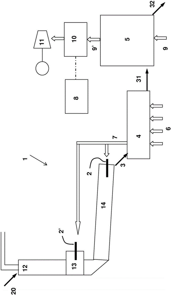
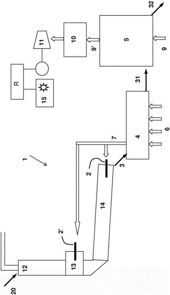
[0045] The invention firstly relates to a process for the production of cement clinker carried out in a continuous production plant 1 with at least one fuel combustion zone 2, 2' for the combustion of inorganic raw materials, wherein the raw materials are converted into clinker by combustion to obtain heat The clinker 3 is then cooled in two consecutive steps, the first cooling step being carried out in the first cooler 4 and the second cooling step being carried out in the second cooler 5 .

[0046] In conventional manner, the continuous production facility may comprise a cyclone preheater 12 , possibly a calciner 13 equipped with one or more burners 2 ′, and a rotary kiln 14 equipped with one or more burners 2 . The hot gas outlet of the calciner 13 can be supplied to the bottom of the cyclone preheater 12 . The hot gas outlet of the rotary kiln 14 may feed the cyclone preheater 12 .

[0047] In this facility, the raw material 20 is preheated in a cyclone preheater 12 , it ...


PUM


Abstract

The invention relates to a cement clinker manufacturing method implemented in a continuous production facility (1) having at least one area (2, 2') for fuel combustion for firing an inorganic raw material. In said method, the raw material is converted into clinker by firing, thus obtaining hot clinker (3), then the hot clinker (3) is cooled in two consecutive steps: a first cooling step, implemented in a first cooler (4); and a second cooling step, implemented in a second cooler (5). According to the invention, the first cooling step is continually carried out by blowing an oxygen gas (6) on the hot clinker to obtain partially cooled clinker, and all the heated oxygen gas (7), created by the first cooler (4), is sent to said at least one combustion area (2, 2') of said facility to be used as a combustion gas by adjusting the amount of oxygen gas, blown in the first cooler, such as to cover the combustion gas needs of said facility without any excess; and the partially cooled clinker (31) is stored in a storage chamber of the second cooler (5) or even a storage chamber associated with said second cooler, and the second cooling step is intermittently carried out on the partially cooled clinker.

Description

technical field [0001] The invention relates to a method for producing cement clinker and a facility for continuously producing cement clinker. [0002] The invention is particularly concerned with the problem of heat losses in such methods and installations. Background technique [0003] Cement clinker production facilities usually consist of a rotary kiln, followed by a clinker cooler before the direction of flow of material being processed by a cyclone preheater. These facilities consume large amounts of energy in the form of fuel, about 3200 megajoules per metric ton of clinker for a modern plant. [0004] A large amount of hot waste flue gas is generated, which is brought into contact with the material, exchanging the heat contained in the gas. Considering the technical and process limitations regarding the exchange, the final flue gas still contains some heat provided by the fuel. On the upstream side with respect to the direction of material flow, the combustion ga...

Claims


Application Information

Patent Timeline
IPC IPC(8): C04B7/47F27B7/36F27B7/38F27D15/02F27D17/00
CPCC04B7/47F27B7/36F27B7/38F27D15/02F27D17/004C04B2290/20F27B7/20F27B7/33F27B7/383C04B7/475Y02P40/121
Inventor 瑟吉·乔盖特
Owner FIVES FCB
Why Eureka
Try Eureka