Improved electrostatic transducer

A transducer, electrostatic technology, used in semiconductor electrostatic transducers, electrostatic transducer speakers, electrostatic transducer microphones, etc., to increase the available frequency range, good acoustic performance, and improve overall quality.

Active Publication Date: 2016-11-23
WARWICK AUDIO TECH LTD
View PDF9 Cites 2 Cited by
  • Summary
  • Abstract
  • Description
  • Claims
  • Application Information

AI Technical Summary

Problems solved by technology

[0006] A problem with this type of electrostatic loudspeaker is getting enough displacement of the membrane

Method used


Image

  • Improved electrostatic transducer
  • Improved electrostatic transducer
  • Improved electrostatic transducer

Examples


Embodiment Construction

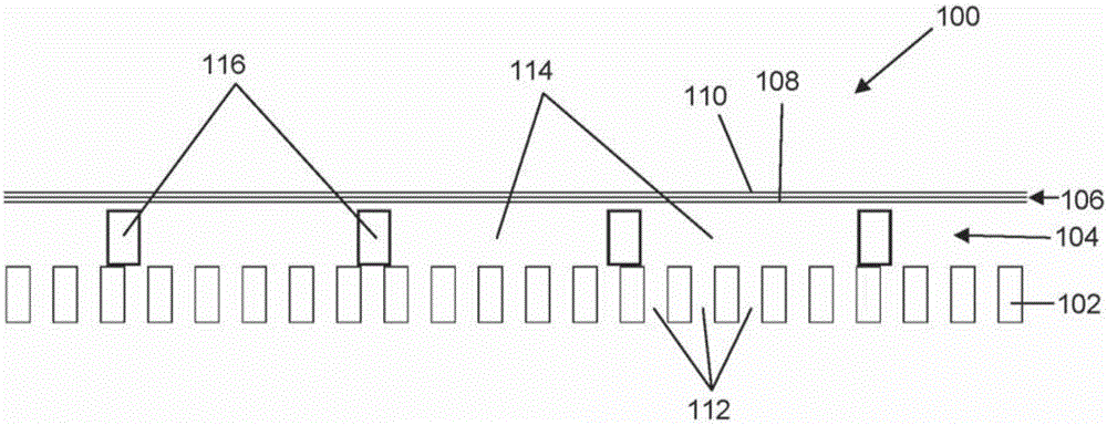
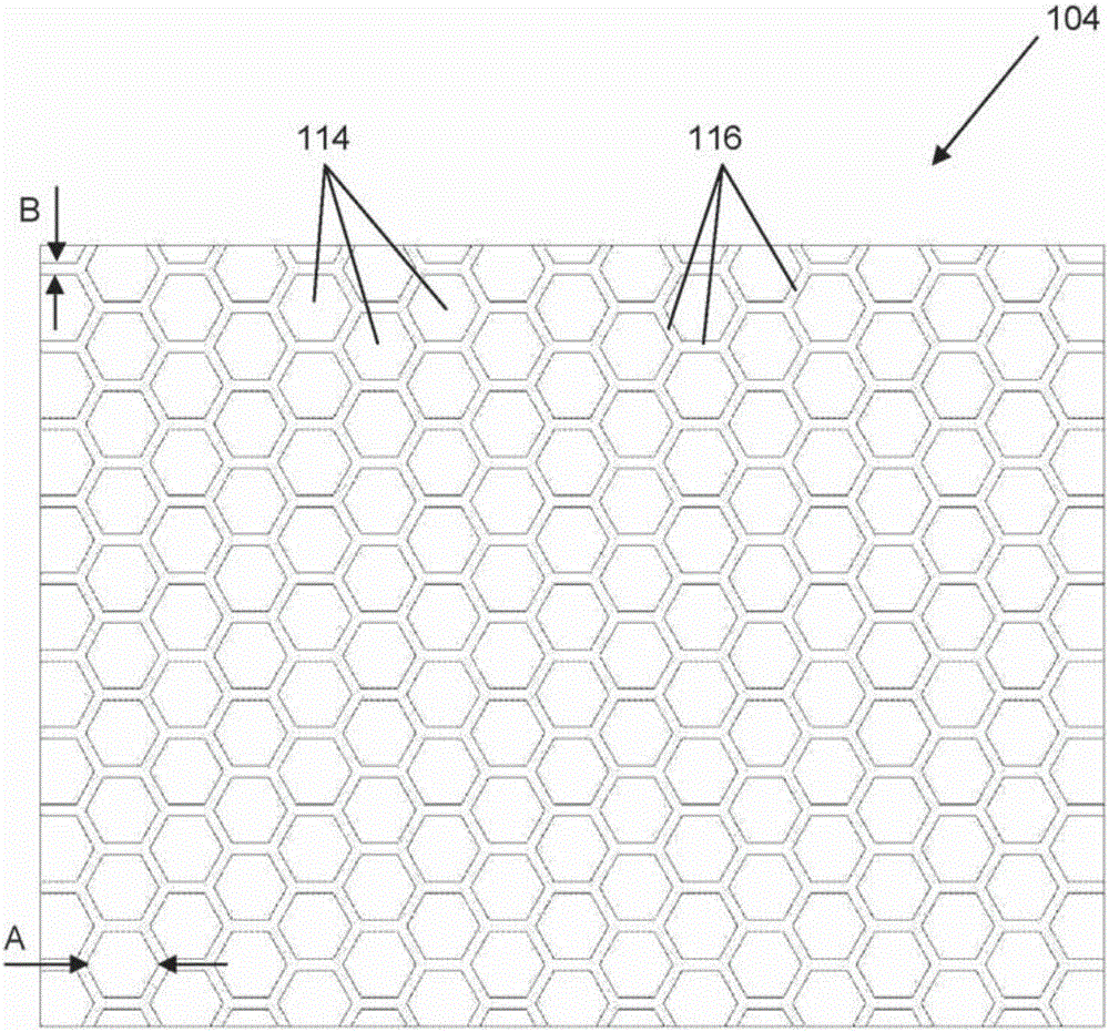
[0048] figure 1 A transducer 100 is shown comprising a backplate member 102, which is 1 mm in thickness. The back plate member 102 is made from aluminum sheet, although other materials or combinations of materials may also be used. The insulating spacer member 104 is provided on the back plate member. The spacer member 104 has a thickness of 0.3 mm and is made of polymer Mylar.

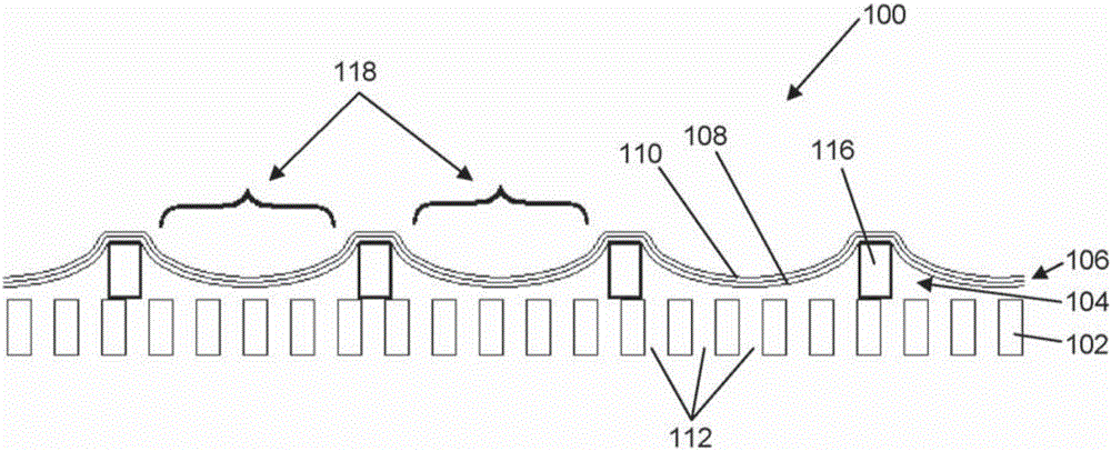
[0049] The composite membrane 106 is disposed on the spacer member 104 . The membrane 106 comprises a 10 μm thick polymer sheet with an aluminum layer 110 disposed thereon by metallization. In this embodiment, the aluminum layer is provided on the surface of the polymer sheet 108 facing away from the spacer member 104 . However, in other embodiments, the film may include a conductive layer on the side of the polymer layer facing the spacer member, or the conductive layer may be sandwiched between two polymer sheets. In some embodiments, there may be a single flexible conductive layer instead of a...


PUM


Abstract

An electrostatic transducer (100) comprises an electrically conductive backplane member (102) having an array of through apertures (112); a spacer member (104) disposed over the backplane member (102), the spacer member (104) having an array of holes (114) therethrough, the holes (114) each having a maximum lateral dimension less than twice a minimum lateral dimension; and a flexible electrically conductive membrane (106) disposed over the spacer member (104). The transducer (100) is arranged in use to apply an electrical potential which gives rise to an attractive electrostatic force between the backplane member (102) and the membrane (106) thereby moving portions of the membrane (106) spanning said holes in the spacer member (104) towards said backplane member (102).

Description

technical field [0001] The present invention relates to an electrostatic transducer, in particular but not exclusively a loudspeaker suitable for reproducing audio signals. Background technique [0002] Conventional electrostatic speakers include a conductive film disposed between two porous conductive backplates to form a capacitor. A DC bias is applied to the membrane, while an AC signal voltage is applied to the two backplates. Hundreds or even thousands of volts may be required. The signal results in an electrostatic force applied to the charged membrane, which moves, driving the air on either side of it. [0003] In US 7095864 an electrostatic loudspeaker comprising a multilayer board is disclosed. An electrically insulating layer is sandwiched between two conductive outer layers. The insulating layer has a circular depression on one side thereof. When a DC bias is applied to the two conductive layers, portions of one of them are attracted to the insulating layer f...

Claims


Application Information

Patent Timeline
Patent Type & Authority Applications(China)
IPC IPC(8): H04R19/02
CPCH04R19/02H04R31/003H04R2201/401H04R2201/403H04R19/04H04R19/005
Inventor 邓肯·比尔森布莱恩·阿特金斯凯文·沃尔什
Owner WARWICK AUDIO TECH LTD
Why Eureka
Try Eureka