Cutting needle advancing and retreating structure of rotary-cut needle and rotary-cut needle with same

A technology of cutting needles and cutting needles, which is applied in trocars, inoculation, ovulation diagnosis, medical science, etc. It can solve the problems of single function and complex structure, and achieve the effect of simple structure and sharp puncture and cutting ability

Pending Publication Date: 2016-11-30
杭州思客医学科技有限公司
View PDF5 Cites 10 Cited by
  • Summary
  • Abstract
  • Description
  • Claims
  • Application Information

AI Technical Summary

Problems solved by technology

[0004] The most advanced puncture rotary cutting equipment in the existing market is mainly foreign brands, such as Anke, Mammotome, Haolejie, which can not only punct

Method used


Image

  • Cutting needle advancing and retreating structure of rotary-cut needle and rotary-cut needle with same
  • Cutting needle advancing and retreating structure of rotary-cut needle and rotary-cut needle with same
  • Cutting needle advancing and retreating structure of rotary-cut needle and rotary-cut needle with same

Examples


Embodiment 1

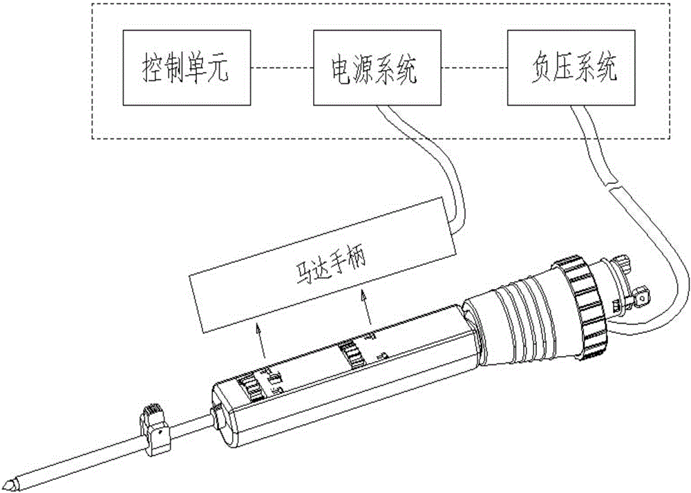
[0033] Such as figure 1 A biopsy rotary cutting system shown includes a rotary cutting needle, a motor handle and a control system. The rotary cutting needle is a sampling and cutting part of the entire rotary cutting system. The motor handle and the entire control system are used in conjunction with it. The control system includes a control unit, a power supply system and a negative pressure system. The motor handle is matched by buckles and gears. Drive the rotary cutting needle for sampling and cutting, and then suck out the sampled and cut tissue into the sampling groove of the rotary cutting needle through the negative pressure system in the control system.

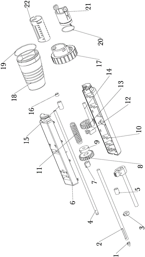
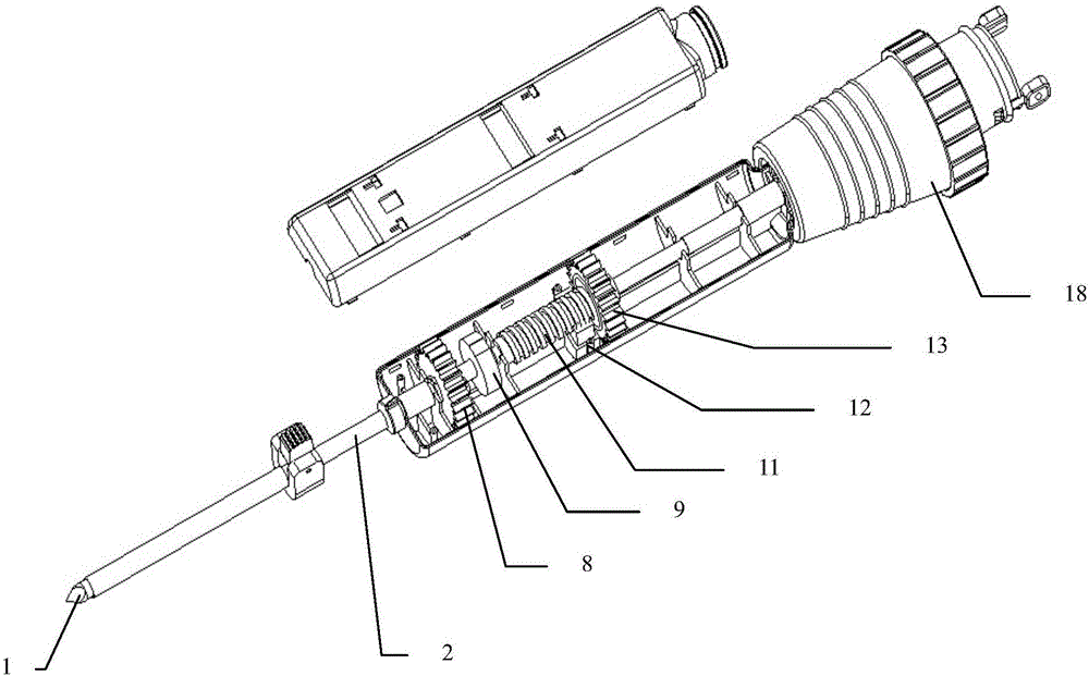
[0034] Such as Figure 2-Figure 6 The rotary cutting needle shown includes a housing, an anti-planting sleeve part, a needle point part, a cutting part and a sampling part, and the housing includes an upper housing 6 and a lower housing 10 connected by buckles. The needle point part includes a needle point 1, a nee...

Embodiment 2

[0044] Such as Figure 7-Figure 10 The rotary cutting needle shown is only different from Embodiment 1 in that the structure of the anti-plantation sleeve part is the same as that of Embodiment 1.

[0045] In this embodiment, the anti-planting sleeve part includes a sleeve b25, a snap ring 26, a cylindrical pin 27 and a snap ring swing rod 28, the snap ring 26 is fixed on one end of the sleeve b25, and the sleeve b25 is Two mutually symmetrical through holes b251 are provided on the side wall at the position of the snap ring 26, and the two snap ring swing rods 28 are symmetrically installed on the snap ring 26, and the middle part of the snap ring swing rod 28 is provided with a first arc groove 282 and a second arc groove 284, the outer diameter of the first arc groove 282 is greater than the outer diameter of the needle sleeve 2, and the outer diameter of the second arc groove 284 is smaller than the needle sleeve 2 The outer diameter of the snap ring swing rod 28 is also ...


PUM


Abstract

The invention relates to a cutting needle advancing and retreating structure of a rotary-cut needle and the rotary-cut needle with the same. The cutting needle advancing and retreating structure of the rotary-cut needle comprises a shell, a needle point part and a cutting part. The needle point part comprises a needle point, a needle sleeve and a gear a. The needle point is welded to one end of the needle sleeve, the other end of the needle sleeve is located in the shell, the gear a is fixed to the other end of the needle sleeve through a gear fixing block, and the side wall of the end, close to the needle point, of the needle sleeve is provided with a cutting through hole. A cutting part comprises an inner sleeve, a worm, a worm fixing block and a gear b, the worm and the gear b are arranged in the shell, one end of the inner sleeve is arranged in the needle sleeve, sawteeth are arranged at one end of the inner sleeve, and a bevel chamfer is arranged. A round hole is formed beside the sawteeth, the other end of the inner sleeve is in close fit with the worm, the gear b is also in close fit with the inner sleeve, and the worm fixing block is fixed to a lower shell and in screw fit with the worm. The rotary-cut needle can fill in the domestic blank through the simple structure and the sharp puncture cutting capacity.

Description

technical field [0001] The invention relates to a medical device, in particular to a cutting needle advancing and retreating structure of a rotary cutting needle and the rotary cutting needle. Background technique [0002] The incidence of breast diseases in my country is very high, and many clinical diseases such as fibroadenomas require surgical resection. The surgical incision is obvious, the trauma is large, it is not beautiful and the cost is high; it is not easy to touch occult lesions in clinical practice or before rake treatment. Fine-needle aspiration cytology or automatic core biopsy gun should be used to confirm the diagnosis before operation, but the possibility of false negative and false positive still exists due to the small sample size, especially for ductal epithelial dysplasia and ductal carcinoma in situ. It cannot provide effective help for clinical treatment, so a simple, safe and reliable technology is introduced, which can not only display the location o...

Claims


Application Information

Patent Timeline
IPC IPC(8): A61B10/02
CPCA61B10/0041A61B10/0275A61B10/0283
Inventor 沈和良刘孟华万继宪
Owner 杭州思客医学科技有限公司
Why Eureka
Try Eureka