Sulfuric acid evaporator for refined acid producing apparatus

A production device and evaporator technology, applied in evaporator adjustment/control, evaporation, sulfur compounds, etc., can solve problems such as poor inspection and maintenance conditions, difficulty in controlling liquid level, high cylinder pressure and thermal expansion compensation requirements, and achieve The effect of convenient medium treatment, not easy to local corrosion, and easy on-site inspection

Inactive Publication Date: 2016-11-30
上海京藤化工有限公司
View PDF6 Cites 4 Cited by
  • Summary
  • Abstract
  • Description
  • Claims
  • Application Information

AI Technical Summary

Problems solved by technology

[0002] combine Figure 4 As shown, the original vertical rising film evaporator has niacin as the medium in the tubes and 0.8MPa low-pressure steam outside the tubes. It has high requirements for the pressure bearing and thermal expansion compensation of the equipment cylinder, and there are many welds on the flower plate, and it is in contact with niacin. , easy to corrode and leak; uneven flow of nicotinic acid, easy to produce uneven evaporation, poor inspection and maintenance conditions, and high difficulty
It is difficult to handle nicotinic acid before maintenance, and there is no liquid level gauge in operation, so it is difficult to control the liquid level. The main corrosion-resistant materials have a narrow application range for the concentration of nicotinic acid, and the leakage failure rate of equipment is high.

Method used


Image

  • Sulfuric acid evaporator for refined acid producing apparatus
  • Sulfuric acid evaporator for refined acid producing apparatus
  • Sulfuric acid evaporator for refined acid producing apparatus

Examples


Embodiment Construction

[0019] The present invention will be further described below in conjunction with the examples, but the protection scope of the present invention is not limited only to the examples.

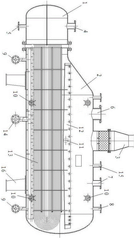
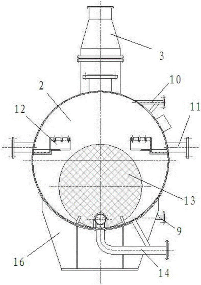
[0020] to combine Figure 1-Figure 3 As shown, a sulfuric acid evaporator used in a refined acid production device has a niacin tank 2 and a water vapor tank 1, and the niacin tank 2 and the water vapor tank 1 are connected by a flange. The bottom of the nicotinic acid tank body 2 is provided with a nicotinic acid inlet 14, and the top is provided with SO 3 The gas outlet 3 is provided with a nicotinic acid outlet 11 on both side walls of the middle part of the nicotinic acid tank body 2 , and a base 16 is arranged at the lower end of the nicotinic acid tank body 2 .

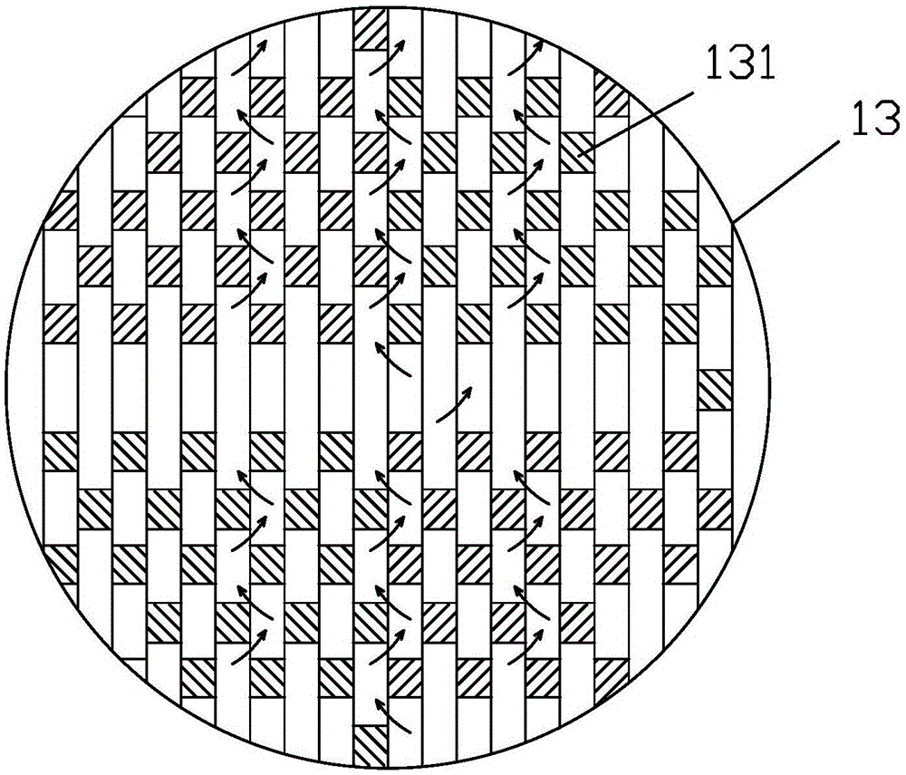
[0021] The top of the water vapor tank 1 is provided with a steam inlet 4, and the bottom is provided with a condensate outlet 5. The nicotinic acid tank 2 is provided with a U-shaped tube bundle 13. The entrance of the U-shaped t...


PUM


Abstract

The invention discloses a sulfuric acid evaporator for a refined acid producing apparatus. The sulfuric acid evaporator is provided with a nicotinic acid tank and a water vapor tank, wherein the bottom portion of the nicotinic acid tank is provided with a nicotinic acid inlet, the top portion of the nicotinic acid tank is provided with a SO3 gas outlet, both side walls on the middle portion of the nicotinic acid tank are respectively provided with a nicotinic acid outlet, the top portion of the water vapor tank is provided with a steam inlet, the bottom portion of the water vapor tank is provided with a condensed water outlet, a U-shaped tube bundle is arranged inside the nicotinic acid tank, the inlet of the U-shaped tube bundle is positioned inside the water vapor tank and is communicated to the steam inlet, the outlet of the U-shaped tube bundle is positioned inside the water vapor tank and is communicated to the condensed water outlet, both sides on the middle portion inside the nicotinic acid tank are respectively provided with an overflow groove, and the bottom portion of the overflow groove is communicated to the nicotinic acid outlet. According to the present invention, the sulfuric acid evaporator is changed into the horizontal evaporator, the U-shaped tube bundle is used, the medium inside the tube bundle is the steam, the nicotinic acid is arranged outside the tube bundle, the actual pressure component of the equipment is reduced, the tube bundle welding seam on the tube nest contacts the steam, no corrosion is generated, and the acid inflow structure and the acid outflow structure of the evaporator consider the uniform flowing so as to ensure the uniform evaporation.

Description

technical field [0001] The invention relates to the related technical field of sulfuric acid production equipment, in particular to a sulfuric acid evaporator used in a refined acid production device. Background technique [0002] to combine Figure 4 As shown, the original vertical rising film evaporator has niacin as the medium in the tubes and 0.8MPa low-pressure steam outside the tubes. It has high requirements for the pressure bearing and thermal expansion compensation of the equipment cylinder, and there are many welds on the flower plate, and it is in contact with niacin. , easy to corrode and leak; uneven flow of nicotinic acid, easy to produce uneven evaporation, poor inspection and maintenance conditions, and high difficulty. It is difficult to handle nicotinic acid before maintenance, and there is no liquid level gauge in operation, so it is difficult to control the liquid level. The main corrosion-resistant materials have a narrow application range for the concen...

Claims


Application Information

Patent Timeline
IPC IPC(8): B01D1/00C01B17/74
CPCB01D1/0082C01B17/74
Inventor 朱军民施惠康朱建祥
Owner 上海京藤化工有限公司
Why Eureka
Try Eureka