Two-electrode distributed micro-gyroscope with upper ring and lower discrete and its preparation method

A micro gyroscope, distributed technology, applied in gyroscope/steering sensing equipment, gyro effect for speed measurement, instrument and other directions, can solve the problem of different electrode distribution schemes of various micro gyroscopes, to increase the number of electrodes, Reduce parasitic capacitance and realize the effect of full angle control

Active Publication Date: 2020-11-06
SHANGHAI JIAO TONG UNIV
View PDF5 Cites 0 Cited by
  • Summary
  • Abstract
  • Description
  • Claims
  • Application Information

AI Technical Summary

Problems solved by technology

[0006] However, the above-mentioned patents only provide the structural scheme of the miniature hemispherical gyroscope with internal discrete electrodes and external discrete electrodes, and cannot provide different electrode distribution schemes for various miniature gyroscopes.

Method used


Image

  • Two-electrode distributed micro-gyroscope with upper ring and lower discrete and its preparation method
  • Two-electrode distributed micro-gyroscope with upper ring and lower discrete and its preparation method
  • Two-electrode distributed micro-gyroscope with upper ring and lower discrete and its preparation method

Examples


Embodiment 1

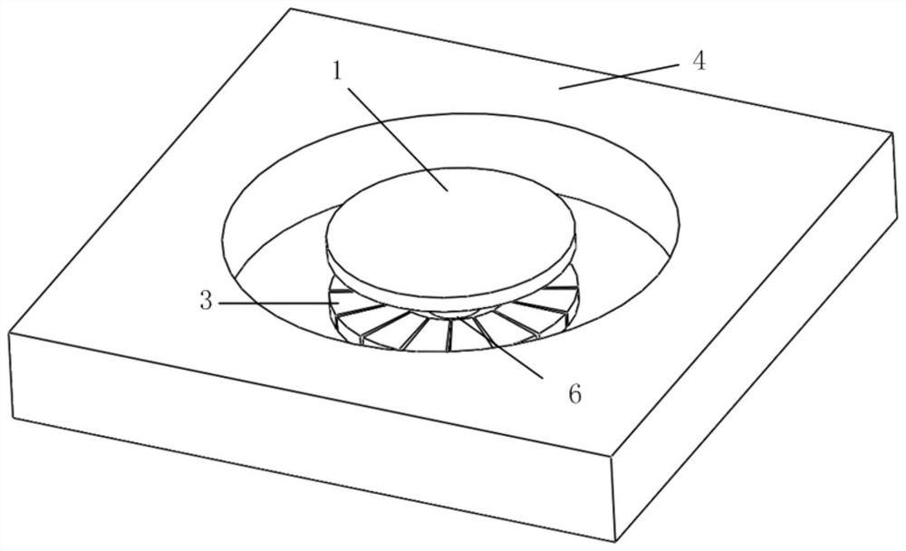
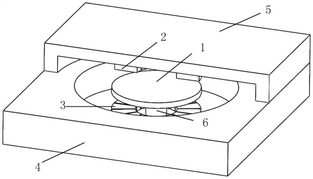
[0047] Such as Figure 1(a)-Figure 1(c) As shown, the present embodiment provides a two-electrode distributed miniature disc resonator gyroscope structure with an upper ring and a lower discrete disc, including:

[0048] A disk-shaped micro-resonator 1;

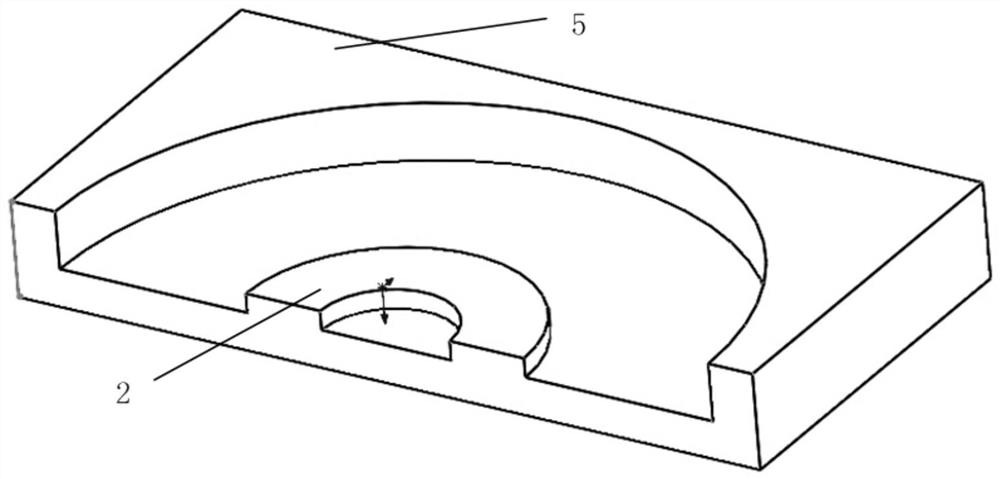
[0049] A ring-shaped integrated upper electrode 2;

[0050] Sixteen evenly distributed lower electrodes 3;

[0051] A monocrystalline silicon substrate 4;

[0052] a glass substrate 5;

[0053] A central fixed support column 6; wherein:

[0054] One end of the central fixed support column 6 is connected to the monocrystalline silicon substrate 4, and the other end of the central fixed support column 6 is connected to the micro-resonator 1 (as shown in FIG. 1(a));

[0055] One of the ring-shaped integrated upper electrodes 2 is arranged on the upper surface of the glass substrate 5 (as shown in Figure 1(b)), and is distributed on the upper side of the micro-resonator 1 (as shown in Figure 1(c) shown); sixteen uniformly di...

Embodiment 2

[0067] Such as Figure 2(a)-Figure 2(c) As shown, the present embodiment provides a two-electrode distributed micro-ring resonant gyroscope structure with an upper ring and a lower discrete ring, including:

[0068] A ring-shaped micro-resonator 1;

[0069] A ring-shaped integrated upper electrode 2;

[0070] Sixteen evenly distributed lower electrodes 3;

[0071] A monocrystalline silicon substrate 4;

[0072] a glass substrate 5;

[0073] A central fixed support column 6; wherein:

[0074] One end of the central fixed support column 6 is connected to the monocrystalline silicon substrate 4, and the other end of the central fixed support column 6 is connected to the micro-resonator 1 (as shown in FIG. 2(a)); The ring-shaped integrated upper electrode 2 is arranged on the surface of the glass substrate 5 (as shown in Figure 2(b)), and distributed on the upper side of the micro-resonator 1 (as shown in Figure 2(c)); Sixteen uniformly distributed lower electrodes 3 are arr...

Embodiment 3

[0082] Such as Figure 3(a)-Figure 3(c) As shown, the present embodiment provides a two-electrode distributed miniature multi-ring resonant gyroscope structure with an upper ring and a lower discrete structure, including:

[0083] A multi-ring micro-resonator 1;

[0084] A ring-shaped integrated upper electrode 2;

[0085] Sixteen evenly distributed lower electrodes 3;

[0086] A monocrystalline silicon substrate 4;

[0087] a glass substrate 5;

[0088] A central fixed support column 6; wherein:

[0089] One end of the central fixed support column 6 is connected to the monocrystalline silicon substrate 4, and the other end of the central fixed support column 6 is connected to the micro-resonator 1 (as shown in Figure 3 (a)); The ring-shaped integrated upper electrode 2 is arranged on the surface of the glass substrate 5 (as shown in Figure 3(b)), and distributed on the upper side of the micro-resonator 1 (as shown in Figure 3(c)); Sixteen uniformly distributed lower ele...


PUM

PropertyMeasurementUnit
radiusaaaaaaaaaa
thicknessaaaaaaaaaa
thicknessaaaaaaaaaa

Abstract

The invention brings forward an upper-ring and lower-discrete double-electrode distributed micro-gyroscope and a preparation method thereof. The micro-gyroscope of the invention comprises a monocrystalline silicon substrate, a central fixed support column, a miniature harmonic oscillator, an upper electrode, a lower electrode and a glass substrate. The product is manufactured by combining an MEMS bulk-silicon machining technology and a surface silicon machining technology. The invention can provide different driving, detection modes and different work patterns. The micro-gyroscope can operate in a system which requires complex control. By respectively utilizing the lower electrode and the upper electrode for driving and detection, parasitic capacitance between a drive electrode and a detecting electrode is reduced, and detection precision is raised.

Description

technical field [0001] The invention relates to a micro-gyroscope in the field of micro-electromechanical technology, in particular to a distributed micro-gyroscope with two electrodes separated on an upper ring and a lower side, and a preparation method thereof. Background technique [0002] Gyroscope is an inertial device that can detect the angle or angular velocity of the carrier, and it plays a very important role in the fields of attitude control, navigation and positioning. With the development of national defense technology and aviation and aerospace industries, the requirements of inertial navigation systems for gyroscopes are also developing in the direction of low cost, small size, high precision, multi-axis detection, high reliability, and adaptability to various harsh environments. Therefore, the importance of MEMS micro-gyro is self-evident. In particular, the miniature disk resonant gyroscope, as an important research direction of the MEMS microgyroscope, has...

Claims


Application Information

Patent Timeline
Patent Type & Authority Patents(China)
IPC IPC(8): G01C19/5684
CPCG01C19/5684
Inventor 张卫平欧彬刘朝阳唐健孙殿竣邢亚亮朱甲强陈畅王晨阳崔峰
Owner SHANGHAI JIAO TONG UNIV
Why Eureka
Try Eureka