High-voltage cable connector with temperature measurement function

A high-voltage cable and temperature measurement function technology, applied in the field of cables, can solve the problems of terminal abnormality, error fluctuating with seasons, and not being widely used, so as to improve the temperature measurement accuracy and ensure safe operation.

Active Publication Date: 2016-11-30
保定合力达电缆附件有限公司
View PDF12 Cites 9 Cited by
  • Summary
  • Abstract
  • Description
  • Claims
  • Application Information

AI Technical Summary

Problems solved by technology

However, when the connection of the terminal is loose, its contact resistance will increase, resulting in an abnormal temperature rise of the terminal when working with high current. If it is not handled in time, it may cause a fire. Therefore, it is necessary to monitor the temperature of the terminal
[0003] There are two main traditional terminal temperature monitoring methods: one is to tie a temperature measurement and transmission device to the terminal, and send the temperature signal to the monitoring center wirelessly. The disadvantage of this method is that the error fluctuates with the seasons, and the measurement error It is too large, and the supporting working battery needs to be replaced once a year. When replacing the battery, the whole device must be in a power failure state, which seriously affects the normal operation of the equipment.
Another method is to use the long-distance infrared temperature measurement method to collect temperature information and upload it. This method is greatly affected by the sensitivity of the temperature measurement equipment and the temperature measurement distance, the error fluctuation is large, and the automatic collection and uploading equipment is complicated and the cost is high.
Due to the above reasons, neither of the existing two terminal temperature monitoring methods has been widely used

Method used


Image

  • High-voltage cable connector with temperature measurement function
  • High-voltage cable connector with temperature measurement function

Examples


Embodiment Construction

[0015] The present invention will be further described below in conjunction with accompanying drawing.

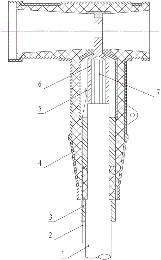
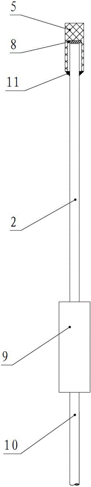
[0016] see figure 1 and figure 2 , The present invention includes a temperature measuring optical fiber 2, a stress cone 3, a terminal sheath 4, a heat-conducting ceramic contact 5, a connecting terminal 6, a photosensitive coating 8, a photoelectric converter 9, a shielding wire 10 and a sealant 11.

[0017] The optical fiber channel (fiber hole) is reserved in the stress cone 3 of the plug-in head, and the temperature-measuring optical fiber 2 passes through the stress cone 3 to reach the terminal 6 inside the plug-in head (configured in the factory). The head of the temperature-measuring optical fiber 2 has a heat-conducting ceramic contact 5, and the heat-conducting ceramic contact 5 is placed on the crimping part of the terminal 6 (the connection between the terminal 6 and the cable core 7) and fixed. The temperature-measuring optical fiber 2 directly obtains temper...


PUM


Abstract

The invention provides a high-voltage cable connector with a temperature measurement function. The high-voltage cable connector with a temperature measurement function is composed of a wiring terminal, a terminal sheath, a stress cone and a temperature measuring device. The wiring terminal is clamped in the terminal sheath. A high-voltage cable penetrates through the stress cone in a cable hole of the terminal sheath to be connected with the wiring terminal in a pressed manner. The temperature measuring device comprises a heat conduction ceramic contact, a temperature measuring optical fiber and a photoelectric converter. The heat conduction ceramic contact is bonded to the wiring terminal. One end of the temperature measuring optical fiber is connected with an input end of the photoelectric converter, and the other end penetrates through the stress cone to be opposite to a photosensitive coating on the heat conduction ceramic contact. A signal output end of the photoelectric converter is connected with a data processor through a shielding wire. According to the invention, the working temperature of the wiring terminal is directly collected by the heat conduction ceramic contact and the temperature measuring optical fiber, and the temperature measuring precision is substantially improved; in addition, the temperature measuring optical fiber is arranged along the cable and the stress cone, the insulation performance of the connector is not influenced, and the safe operation of the high-voltage cable connector is ensured.

Description

technical field [0001] The invention relates to a high-voltage cable plug-in plug capable of real-time monitoring of the working temperature of an internal terminal, belonging to the technical field of cables. Background technique [0002] The plug-in head is an important part of the high-voltage line, mainly including the terminal block (European terminal), the terminal sheath and the stress cone. The cone is then crimped together with the terminal block. If the connection between the terminal and the high-voltage cable is reliable, and the terminal screws are fastened normally, the temperature of the terminal will be basically normal under high current working conditions, and there will be no abnormal temperature rise. However, when the connection of the terminal is loose, its contact resistance will increase, resulting in an abnormal temperature rise of the terminal when working with high current. If it is not handled in time, it may cause a fire. Therefore, it is necess...

Claims


Application Information

Patent Timeline
Patent Type & Authority Applications(China)
IPC IPC(8): G01K11/32H01R13/66
CPCH01R13/6683G01K11/32
Inventor 史宏杰袁利军王俊鹏
Owner 保定合力达电缆附件有限公司
Why Eureka
Try Eureka