Coaxial cavity filter

A filter and coaxial cavity technology, applied in waveguide-type devices, electrical components, circuits, etc., can solve problems such as restricting filter cost control, complex processing and assembly processes, and inability to reuse products, and achieves convenient equipment maintenance. The effect of simplifying the production process and improving the utilization rate of materials

Inactive Publication Date: 2016-11-30
TONGYU COMM INC
View PDF4 Cites 3 Cited by
  • Summary
  • Abstract
  • Description
  • Claims
  • Application Information

AI Technical Summary

Problems solved by technology

The weight of the existing coaxial cavity filter is mainly the filter housing, the larger the filter, the greater the proportion of the weight of the housing, which seriously restricts the cost control of the filter
Moreover, the cavity structure inside the filter is integrated with the filter housing. A defect in a certain cavity will easily lead to the scrapping of the enti

Method used


Image

  • Coaxial cavity filter
  • Coaxial cavity filter
  • Coaxial cavity filter

Examples


Embodiment 1

[0034] Please also refer to Figure 4 to Figure 9 , is a schematic structural diagram of a coaxial cavity filter provided by an embodiment of the present invention. For ease of description, only parts related to the embodiments of the present invention are shown.

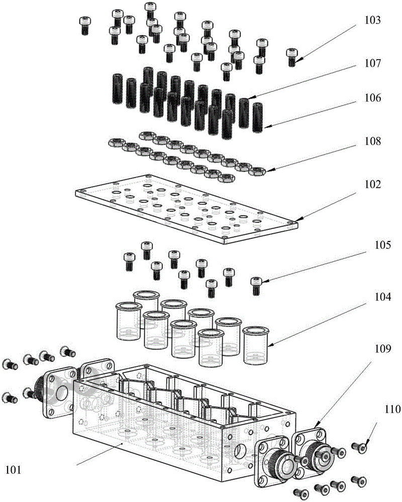
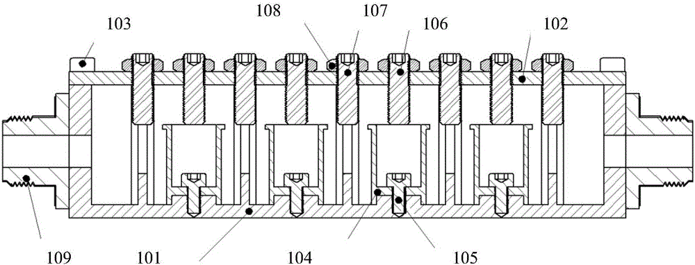
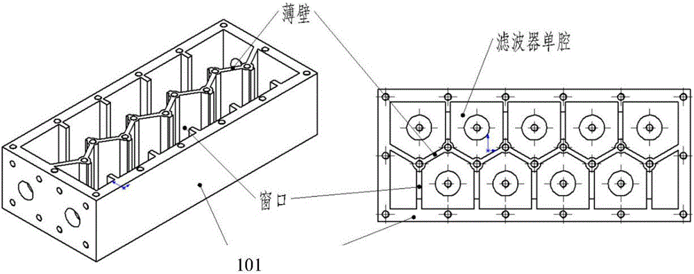
[0035] The coaxial cavity filter includes: a modular single cavity 200, a resonant rod 201, a resonant rod fastening pin 202, a spring washer 203, a cover plate 204, a tuning screw 205, a coupling screw 206, a fastening nut 207 and a filter connector 208.

[0036] Wherein, a groove is opened on the cover plate 204, and the groove is used for installing the modularized single cavity 200, and screw holes for installing the tuning screw 205 and the coupling screw 206 are also provided on the cover plate 204, such as Figure 6 shown. The upper end of the modular single chamber 200 is fixed in the groove of the cover plate by welding or conductive glue bonding or pressing, so as to be closed with the cover plate 204 t...

Embodiment 2

[0046] Please also refer to Figure 10 to Figure 12 , is a schematic structural diagram of the coaxial cavity filter provided by Embodiment 2 of the present invention. For ease of description, only parts related to the embodiments of the present invention are shown.

[0047] The coaxial cavity filter includes: a modular single cavity 300 , a locking collar 301 , a resonant rod 302 , a cover plate 303 , a tuning screw 304 , a coupling screw 305 , a fastening nut 306 and a filter connector 307 .

[0048] Wherein, a slot is opened on the cover plate 303 for installing the modular single chamber 300 , and screw holes for installing the tuning screw 304 and the coupling screw 305 are also provided on the cover plate 303 . The upper end of the modular single cavity 300 is fixed in the groove of the cover plate by welding or conductive glue bonding or pressing, so as to be closed with the cover plate 303 to form a resonant cavity. At the same time, a locking hoop 301 is provided on...


PUM


Abstract

The invention discloses a coaxial cavity filter. The coaxial cavity filter comprises single modular cavities, resonant rods, a cover plate, tuning screws, coupling screws and filter joints, wherein the cover plate is provided with grooves, the grooves are used for installing the single modular cavities, the upper ends of the single modular cavities are fixed in the cover plate grooves so as to be enclosed with the cover plate to form resonant cavities; the multiple single modular cavities are spliced together to form connected resonant cavities so as to form a filter cavity; the resonant rods are arranged at the bottom portions inside the single modular cavities; the tuning screws and the coupling screws are arranged on the cover plate and partially extend into the resonant cavities; and the filter joints are fixed on the single modular cavities at the head end and the tail end of the coaxial cavity filter. The coaxial cavity filter does not need a filter housing, is simple in processing and assembling process and good in interchangeability and can be repeatedly used.

Description

【Technical field】 [0001] The invention relates to the technical field of communication equipment, in particular to a coaxial cavity filter. 【Background technique】 [0002] A filter is a frequency filtering device, which selects signals in the required frequency band and suppresses signals in the unnecessary frequency band. Filters are widely used in communication fields such as radio frequency and microwave. At present, the most widely used filter in the radio frequency and microwave frequency band is the coaxial cavity filter. The coaxial cavity filter has good electromagnetic shielding, compact structure, and low passband insertion loss. In the case of capacitive loading, the coaxial cavity filter can be made very small, and has a high square coefficient and high power Advantages of high capacity. figure 1 It is a three-dimensional exploded view of a typical structure of a coaxial cavity filter in the prior art, figure 2 It is a cross-sectional view of a filter in the ...

Claims


Application Information

Patent Timeline
IPC IPC(8): H01P1/205
CPCH01P1/205
Inventor 蔡辉巨刚吴中林袁进华李龙兴吕家泉
Owner TONGYU COMM INC
Why Eureka
Try Eureka