Terminal with wire, manufacturing method of terminal with wire, and wire harness
A manufacturing method and wire technology, which are applied in the field of terminals with wires, the manufacture of terminals with wires, and the field of wiring harnesses, and can solve the problems of oxide film thickness and the like
- Summary
- Abstract
- Description
- Claims
- Application Information
AI Technical Summary
Problems solved by technology
Method used
Image
Examples
no. 1 example
[0120] The terminals with wires are constructed to include aluminum wires and crimp terminals. The aluminum electric wire is configured to include an aluminum or aluminum alloy conductor and an insulating resin coating member covering the conductor. The resin-coated member was removed from the aluminum electric wire to form a conductor exposed portion. The crimp terminal includes a caulking portion as a crimp portion. In the caulking portion, a conductor caulking sheet and a covered member caulking sheet are formed. Terminals with wires The caulking portion is crimped to the conductor exposed portion to form a wire-to-terminal connection. Then, an anticorrosion portion is formed to cover the wire-terminal connection portion. The anti-corrosion portion is formed such that a voltage is applied between the crimp terminal and the metal nozzle, and the electrified anti-corrosion material is supplied from the metal nozzle to the wire-terminal connection portion in a state of bein...
example
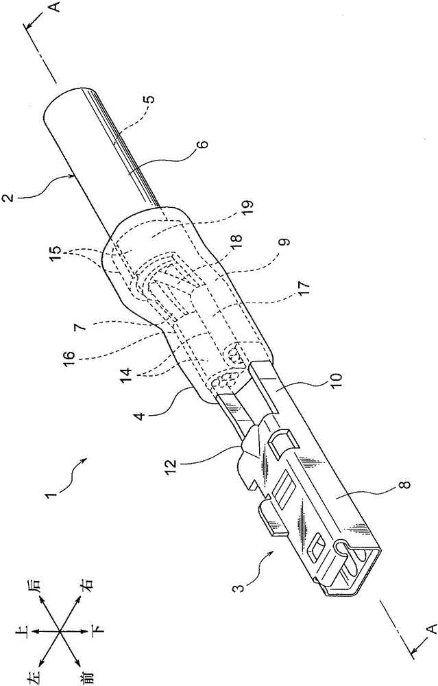
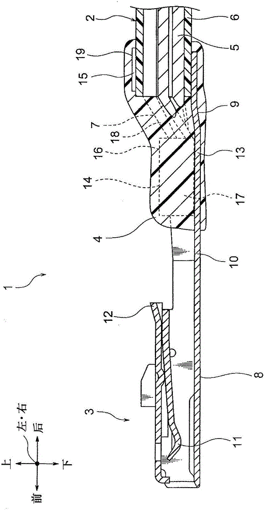
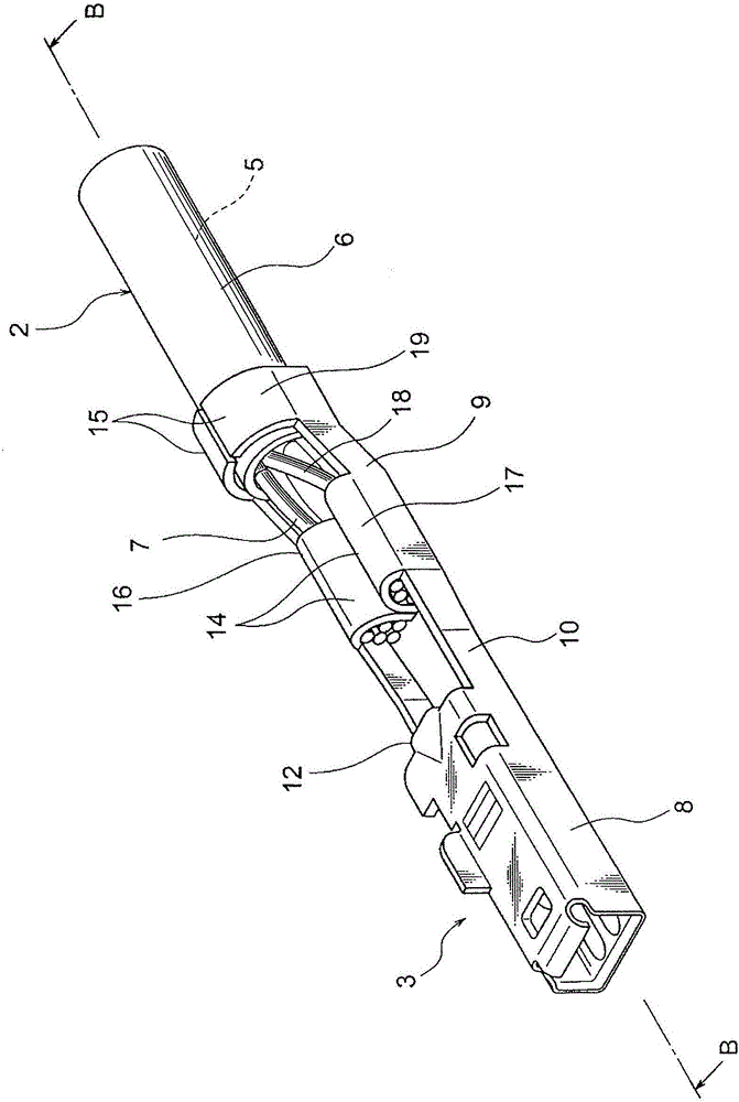
[0122] Hereinafter, examples of the first embodiment will be described with reference to the drawings. figure 1 is a perspective view illustrating the terminal with electric wires of the first embodiment of the present invention. in addition, figure 2 is along figure 1 A cross-sectional view taken along the line A-A, image 3 is a perspective view of a terminal with wires before forming the anti-corrosion portion, and Figure 4 is along image 3 A cross-sectional view taken along the line B-B. also, Figure 5 is a perspective view of a terminal with electric wires for describing the manufacturing method in the first embodiment of the present invention, Image 6 is along Figure 5 A cross-sectional view taken along the line A-A, and Figure 7 is a diagram for describing the procedure of the manufacturing method in the first embodiment of the present invention. also, Figure 8 is a perspective view of the connector of the wire harness in the first embodiment of the ...
no. 2 example
[0163] in the above reference Figure 13A with 13B In the conventional technique described, the anti-corrosion material 117 is dripped from the respective nozzles 116 of the two dispensers. Then, the anticorrosion material 117 thus dropped and coated hardens to form the anticorrosion portion 115 . In the forming method of the conventional example, it takes time to harden the anticorrosion material 117, and when liquid dripping or sink marks occur, there is a problem in manufacturability. In addition, in the case where the coverage range of the anticorrosion material 117 is not clearly defined, the anticorrosion portion 115 may be insufficiently formed.
[0164] Furthermore, in the above conventional art, in the case where bubbles are generated in the coated anticorrosion material 117 and the bubbles are broken when the anticorrosion material 117 is hardened, the function of the anticorrosion portion 115 may deteriorate.
PUM
 Abstract
Description
Claims
Application Information
 - R&D
- Intellectual Property
- Life Sciences
- Materials
- Tech Scout
- Unparalleled Data Quality
- Higher Quality Content
- 60% Fewer Hallucinations
Browse by: Latest US Patents, China's latest patents, Technical Efficacy Thesaurus, Application Domain, Technology Topic, Popular Technical Reports.
© 2025 PatSnap. All rights reserved.Legal|Privacy policy|Modern Slavery Act Transparency Statement|Sitemap|About US| Contact US: help@patsnap.com


