A matching welding method for hoisting connection lugs of co-lifting drilling rig

A drilling rig and lug technology, applied in welding equipment, auxiliary welding equipment, welding/cutting auxiliary equipment, etc., can solve the problem of poor welding accuracy of drilling rig and base lifting connection lugs, poor component stress, and on-site operation. Difficulties and other problems, to achieve the effect of reducing the inconsistency of welding benchmarks, reducing welding difficulty, and strong on-site operability

Active Publication Date: 2017-10-31
BAOJI PETROLEUM MASCH CO LTD +2
View PDF5 Cites 0 Cited by
  • Summary
  • Abstract
  • Description
  • Claims
  • Application Information

AI Technical Summary

Problems solved by technology

[0004] The purpose of the present invention is to provide a method for matching and welding the hoisting connection lugs of the same-lift drilling rig, which solves the problem of poor overall flatness and poor measurement reference of the drilling rig test site when the lifting and connecting parts of the existing co-lifting drilling rig are matched and welded. The problems caused by poor matching and welding accuracy of the lifting connection lug plate of the drilling rig and the base, difficulty in on-site operation, and poor stress on each component during the lifting process of the drilling rig

Method used


Image

  • A matching welding method for hoisting connection lugs of co-lifting drilling rig
  • A matching welding method for hoisting connection lugs of co-lifting drilling rig
  • A matching welding method for hoisting connection lugs of co-lifting drilling rig

Examples


Embodiment Construction

[0020] The present invention will be described in detail below in conjunction with the accompanying drawings and specific embodiments.

[0021] Up, down, left, and right in the text are subject to the orientation shown in the figure, and so on for the actual installation position.

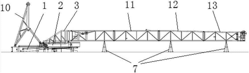
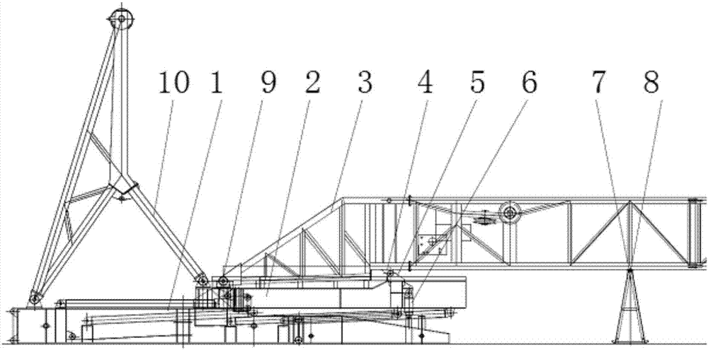
[0022] refer to figure 1 , figure 2 The overall structure of the same-lift drilling rig derrick adopted in the method of the present invention is in a horizontal state, the lower base 1 of the drilling rig is arranged on the cement floor of the drilling rig test well site, and is used to support and install other parts of the drilling rig; A herringbone frame 10 is installed at the end, which is used for lifting of the drilling rig and fixing after lifting; the front end of the lower base 1 of the drilling rig is equipped with the upper base 2 of the drilling rig, and the lower base 1 and the upper base 2 of the drilling rig pass through multiple The column and the inclined frame are connected; ...


PUM


Abstract

The invention discloses an assembling and welding method for elevating connecting lug bases of a synchronous elevating type drilling machine. The method comprises the steps that firstly, the center coaxiality and position degree of pin shaft holes of the synchronous elevating connecting double-lug base are guaranteed on a workbench; secondly, the overall planeness of a drilling machine lower base is guaranteed on the well drilling site; thirdly, a lower derrick section, a middle derrick section, a middle upper derrick section and an upper derrick section are sequentially connected in the horizontal direction, and supporting assemblies are arranged on the lower surfaces of the sections; fourthly, an adjusting gasket I is additionally arranged between each supporting assembly and the lower surface of a front stand column of the corresponding derrick section; fifthly, the synchronous elevating connecting single-lug base and the synchronous elevating connecting double-lug base are hinged, and the lower surface of the synchronous elevating connecting single-lug base is suspended; sixthly, a jacking oil cylinder is utilized for conducting adjustment, and an adjusting gasket II is arranged below the drilling machine lower base and a drilling machine upper base; seventhly, the synchronous elevating connecting single-lug base is assembled and welded to the drilling machine upper base, and then nondestructive testing is conducted; and eighthly, it is guaranteed that the drilling machine upper base is arranged in place while a drilling machine derrick is elevated in place. The method is simple, feasible and high in assembling quality.

Description

technical field [0001] The invention belongs to the technical field of drilling and production equipment manufacturing, and relates to a matching welding method for lifting and connecting lugs of a co-lifting drilling rig. Background technique [0002] As the name implies, the same-lift drilling rig uses a lifting system to simultaneously lift the derrick and base of the drilling rig into place. Therefore, this type of drilling rig has the advantages of simple installation of the lifting system, high lifting and lowering efficiency of the derrick and base, and low operational safety risks. And other characteristics, significantly reduce the labor intensity of the operator, and improve the efficiency of drilling rig relocation and on-site installation. [0003] Since the drilling rig mast and the base cannot be assembled and lifted as a single piece, the connecting lugs for the simultaneous lifting of the drilling rig mast and the base cannot be configured during the producti...

Claims


Application Information

Patent Timeline
Patent Type & Authority Patents(China)
IPC IPC(8): B23K37/00
CPCB23K37/00
Inventor 罗强雷广进刘宏亮任小伟高超杰
Owner BAOJI PETROLEUM MASCH CO LTD
Why Eureka
Try Eureka