
Nuclear power semi-ring machining method

A processing method and nuclear power technology, applied in the field of mechanical processing, can solve the problems of reducing welding quality, increasing work difficulty in subsequent welding, unable to guarantee the machining accuracy of nuclear power semi-rings, etc., so as to improve turning processing efficiency and reduce axial and radial The effect of resisting force and reducing stress and deformation

Inactive Publication Date: 2016-12-07
HARBIN TURBINE
View PDF7 Cites 4 Cited by
  • Summary
  • Abstract
  • Description
  • Claims
  • Application Information

AI Technical Summary

Problems solved by technology

[0003] In order to solve the problems that the existing technological scheme cannot guarantee the processing accuracy of the nuclear power semi-ring, increase the difficulty of subsequent welding and reduce the welding quality, the present invention further proposes a nuclear power semi-ring processing method

Method used


Image

  • Nuclear power semi-ring machining method
  • Nuclear power semi-ring machining method
  • Nuclear power semi-ring machining method

Examples


specific Embodiment approach 1

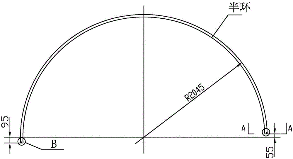
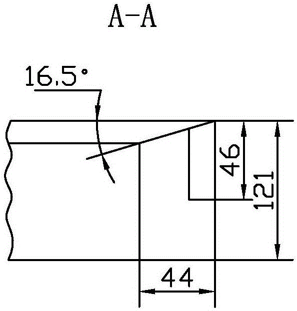
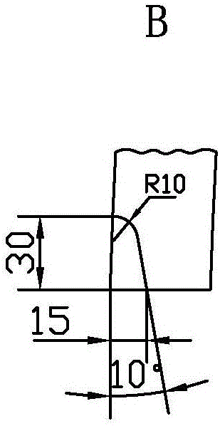
[0019] Specific implementation mode one: combine Figure 1 to Figure 7 Describe this embodiment, the concrete steps of a kind of nuclear power semi-ring processing method described in this embodiment are as follows:

[0020] Step 1, semi-ring blank casting;

[0021] Step 2. Turning the surface of the half ring to 121mm on a vertical lathe, and turning the two planes to 122mm;

[0022] Step 3. Draw the inner hole, outer circle line and surface lines at both ends on the half ring, and mark the 55mm size on the right side according to the 95mm size;

[0023] Step 4, milling the two ends of the half ring on the boring machine, and both ends of the half ring are processed with a size of 95mm;

[0024] Step 5. Turn the quasi-inner hole of the semi-ring on a vertical lathe, and the outer circle is 3mm to 5mm;

[0025] Step 6. The fitter fits the welded tension bars on the half ring;

[0026] Step 7, electric welding and welding of tension bars;

[0027] Step 8, performing heat t...

specific Embodiment approach 2

[0032] Specific implementation mode two: combination Figure 1 to Figure 7 To illustrate this embodiment, the cutting parameters in Step 2 of a nuclear power semi-ring processing method described in this embodiment are: rotational speed 6r / min, feed rate 0.25mm / r, and cutting depth 3mm. Other components and connections are the same as those in the first embodiment.

specific Embodiment approach 3

[0033] Specific implementation mode three: combination Figure 1 to Figure 7 To illustrate this embodiment, the cutting parameters in Step 4 of a nuclear power semi-ring processing method described in this embodiment are: rotational speed 240r / min, feed rate 0.2mm / r, cutting depth 4mm. Other components and connections are the same as those in the first embodiment.


PUM


Abstract

The invention belongs to the field of machining and relates to a machining method, in particular to a nuclear power semi-ring machining method. The problems that according to an existing technological scheme, the machining precision of a nuclear power semi-ring cannot be guaranteed, the working difficulty is increased for subsequent welding, and the welding quality is lowered are solved. The machining method specifically comprises the steps that firstly, a semi-ring blank is formed through casting; secondly, the surface of the semi-ring is turned by 121 mm on a vertical lathe, and the two planes are turned to 122 mm; thirdly, an inner hole, the outer circle line and two end face lines are marked on the semi-ring, and a line is marked in the position 55 mm away from the right side according to the dimension of 95 mm; fourthly, the two end faces of the semi-ring are milled on a boring mill, and the two end faces of the semi-ring are machined according to the dimension of 95mm; fifthly, the standard inner hole of the semi-ring is turned on the vertical lathe, and the volume of the outer circle is 3-5 mm; sixthly, tie bars are welded to the semi-ring in a matched mode by a bench worker; and seventhly, the tie bars are welded through electric welding.

Description

technical field [0001] The invention relates to a processing method, in particular to a nuclear power semi-ring processing method, and belongs to the field of mechanical processing. Background technique [0002] After the nuclear power semi-ring is processed accurately, it is welded to the inner hole of the partition to form the outer ring part of the partition. The material of the nuclear power semi-ring is 022Cr19Ni10. There are two difficulties in the processing of this part: first, the structural rigidity of the part is poor, and the stress after rough machining Deformation affects the manufacturing accuracy of the part. The second is that the material of the part is stainless steel. When turning, the machinability is not good, and the processing efficiency of the conventional processing method is low. In order to improve the processing accuracy and processing efficiency of this part, a nuclear power semi-ring processing method has been developed. Contents of the inve...

Claims


Application Information

Patent Timeline
Patent Type & Authority Applications(China)
IPC IPC(8): B23P15/00
CPCB23P15/00
Inventor 孙盛丽崔会彬魏成双胡迪胡卫杰李辉尹若枫赵祎昕武申萍吕岩峰
Owner HARBIN TURBINE
Learn More