
Hydraulic lifting device

A technology of hydraulic lifting and supporting devices, applied in the direction of lifting devices, lifting frames, etc., can solve the problems of affecting work efficiency, increasing labor costs, wasting manpower, etc., and achieve the effect of saving manpower, reducing operating costs and convenient operation

Inactive Publication Date: 2016-12-07
ANHUI KELI ELECTRIC MFG
View PDF0 Cites 1 Cited by
  • Summary
  • Abstract
  • Description
  • Claims
  • Application Information

AI Technical Summary

Problems solved by technology

[0002] In some mechanized workshops, because the products on the assembly line need to be moved according to the needs of the assembly line, the current general method is to use manpower to move, which wastes manpower and time, and affects work efficiency, especially in two On the upper and lower parallel assembly lines, the products on the lower assembly line need to be transported to the upper assembly line. The current method is generally to use manpower to transport or move, which is easy to waste time and increase labor costs. The quality of the product is affected during the conveying process, and the processing accuracy may also be affected due to improper placement when placed on the upper assembly line

Method used


Image

  • Hydraulic lifting device
  • Hydraulic lifting device

Examples


Embodiment Construction

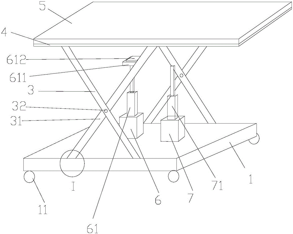
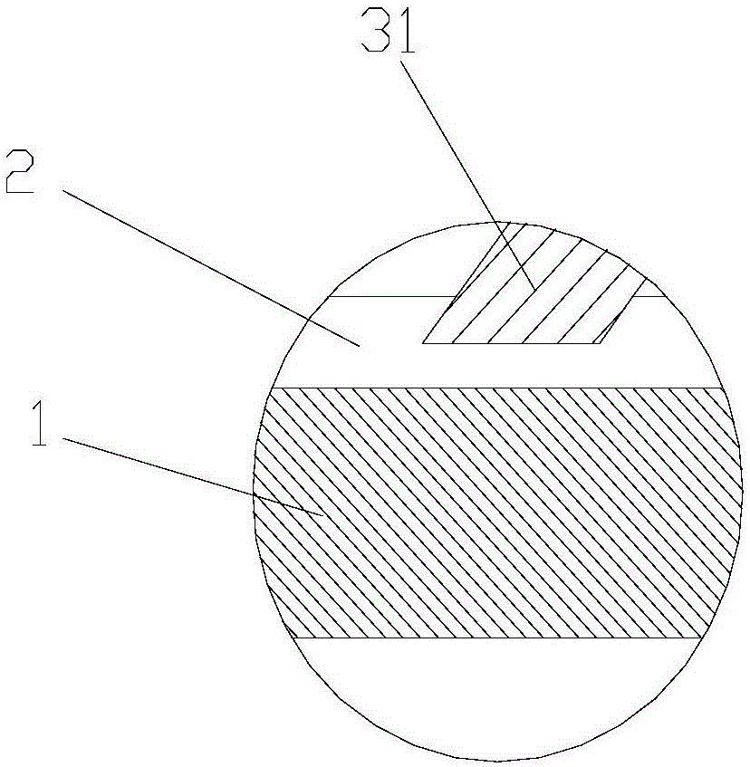
[0016] Such as figure 1 , figure 2 As shown, a hydraulic lifting device includes a base 1. Two parallel chutes 2 are arranged on the base 1. Two support devices 3 are arranged on the chute 2. A support frame 4 is provided on the support device 3. The support frame 4 is provided with a supporting plate 5, and the support device 3 includes two mutually intersecting struts 31, and bolts 32 are arranged at the intersections, and every two struts 31 slide on each chute 2 respectively, and a support device 3 is provided between An air pump 6 is provided, and a pressure rod 61 is arranged on the air pump 6 , and the top end of the pressure rod 61 is connected to the supporting plate 5 .

[0017] In order to facilitate the movement or positioning of the device, universal wheels 11 are provided at the bottom of the base 1 .

[0018] In order to meet the needs of the parts to be conveyed, the pallet 5 is set as a pull-out pallet, which can be easily replaced when damage occurs to the...


PUM


Abstract

The invention discloses a hydraulic lifting device. The device comprises a base, two sliding grooves placed in parallel are formed in the base, two supporting devices are arranged on the sliding grooves, and a supporting frame is arranged on the supporting devices; a supporting plate is arranged on the supporting frame, each supporting device comprises two crossing supporting rods, a bolt is arranged at the crossing position, every two supporting rods slide on each sliding groove, an air pump is arranged between the supporting devices, a pressing rod is arranged on the air pump, and the top end of the pressing rod is connected to the supporting plate; the hydraulic lifting device is simple in structure and convenient to operate, manual operation is saved, operation cost is reduced, a product can conveniently move and is conveniently conveyed on an upper and lower assembly line, in the conveying process, product quality is not affected, and the influence of improper placement on the placing position is avoided.

Description

technical field [0001] The invention relates to a lifting device, in particular to a hydraulic lifting device. Background technique [0002] In some mechanized workshops, because the products on the assembly line need to be moved according to the needs of the assembly line, the current general method is to use manpower to move, which wastes manpower and time, and affects work efficiency, especially in two On the upper and lower parallel assembly lines, the products on the lower assembly line need to be transported to the upper assembly line. The current method is generally to use manpower to transport or move, which is easy to waste time and increase labor costs. The quality of the product is affected during the conveying process, and the processing accuracy may also be affected due to improper placement when placed on the upper assembly line. Contents of the invention [0003] The purpose of the present invention is aimed at the defect of using human power to move produc...

Claims


Application Information

Patent Timeline
IPC IPC(8): B66F7/08
CPCB66F7/085B66F7/065
Inventor 马形山
Owner ANHUI KELI ELECTRIC MFG
Learn More