Telescopic steel formwork

A technology of steel formwork and steel slats, which is applied to the preparation of formwork/formwork components, formwork/formwork/work frames, and building components on site. Easy to run out of pulp and other problems, to achieve the effect of uniform and beautiful natural joints of the formwork, speed up construction, and reduce construction costs

Active Publication Date: 2018-10-12
CHINA HUAYE GROUP
View PDF5 Cites 0 Cited by
  • Summary
  • Abstract
  • Description
  • Claims
  • Application Information

AI Technical Summary

Problems solved by technology

However, the traditional wedge-shaped formwork can only be made by hand on site, the production process is complicated, and it is not suitable for mass production. Therefore, the production efficiency of the wedge-shaped formwork is low, and it also occupies the construction site; the installation of the wedge-shaped formwork is also complicated.
At the same time, the wedge-shaped formwork is not easy to be connected and reinforced with its adjacent formwork, resulting in uneven and tight joints of the formwork, easy to run out of the concrete during the construction process, the concrete surface will be misaligned and other uneven phenomena, and the wedge-shaped joint formed on the concrete surface is also difficult. Irregular, unsightly
In short, the use of wedge-shaped formwork is labor-intensive and the concrete appearance is not ideal

Method used


Image

  • Telescopic steel formwork
  • Telescopic steel formwork
  • Telescopic steel formwork

Examples


Embodiment Construction

[0025] The present invention will be further described below in conjunction with the embodiments and accompanying drawings.

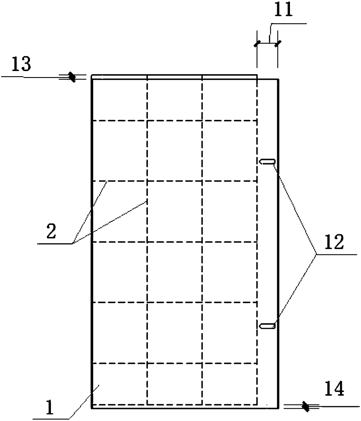
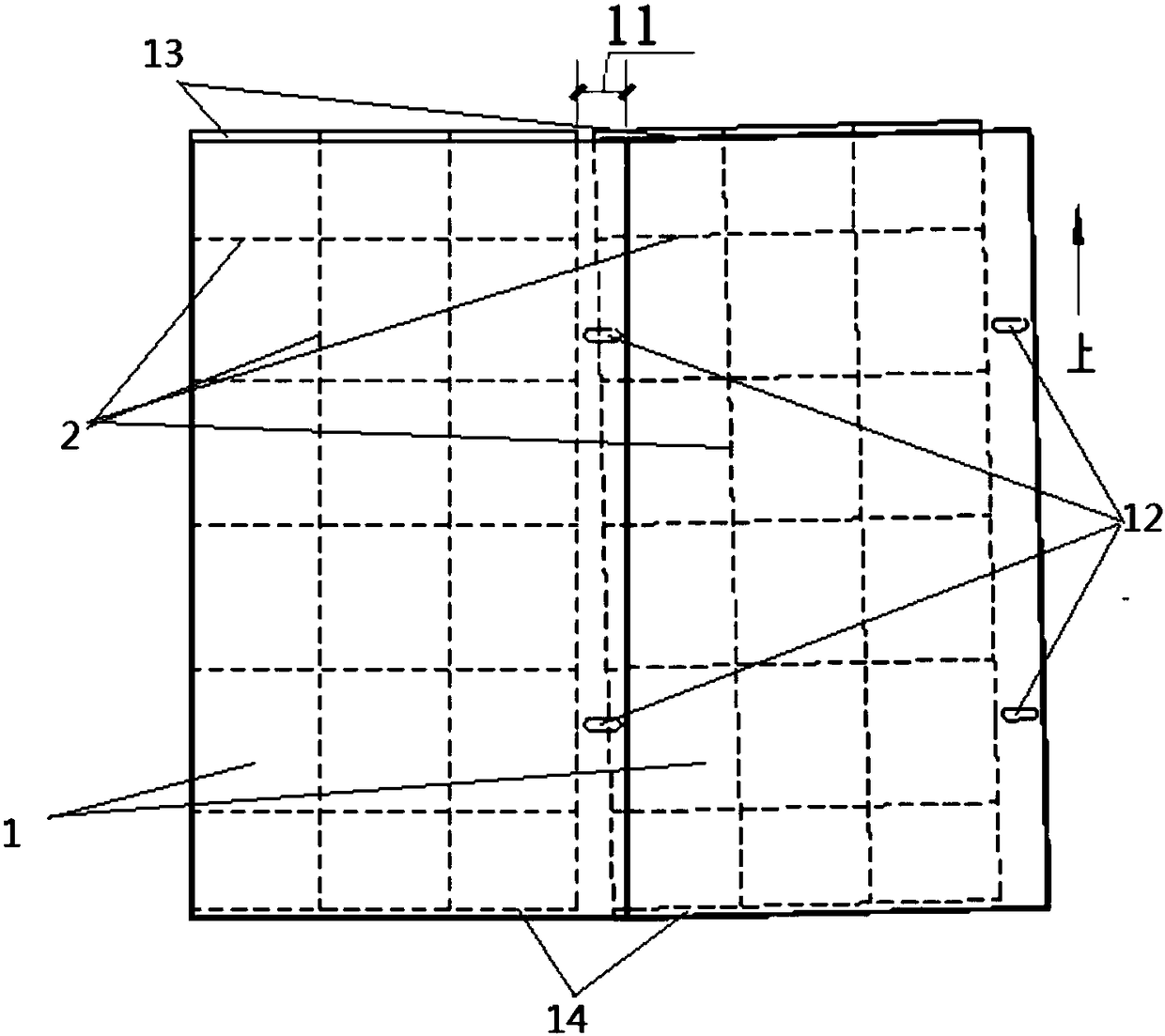
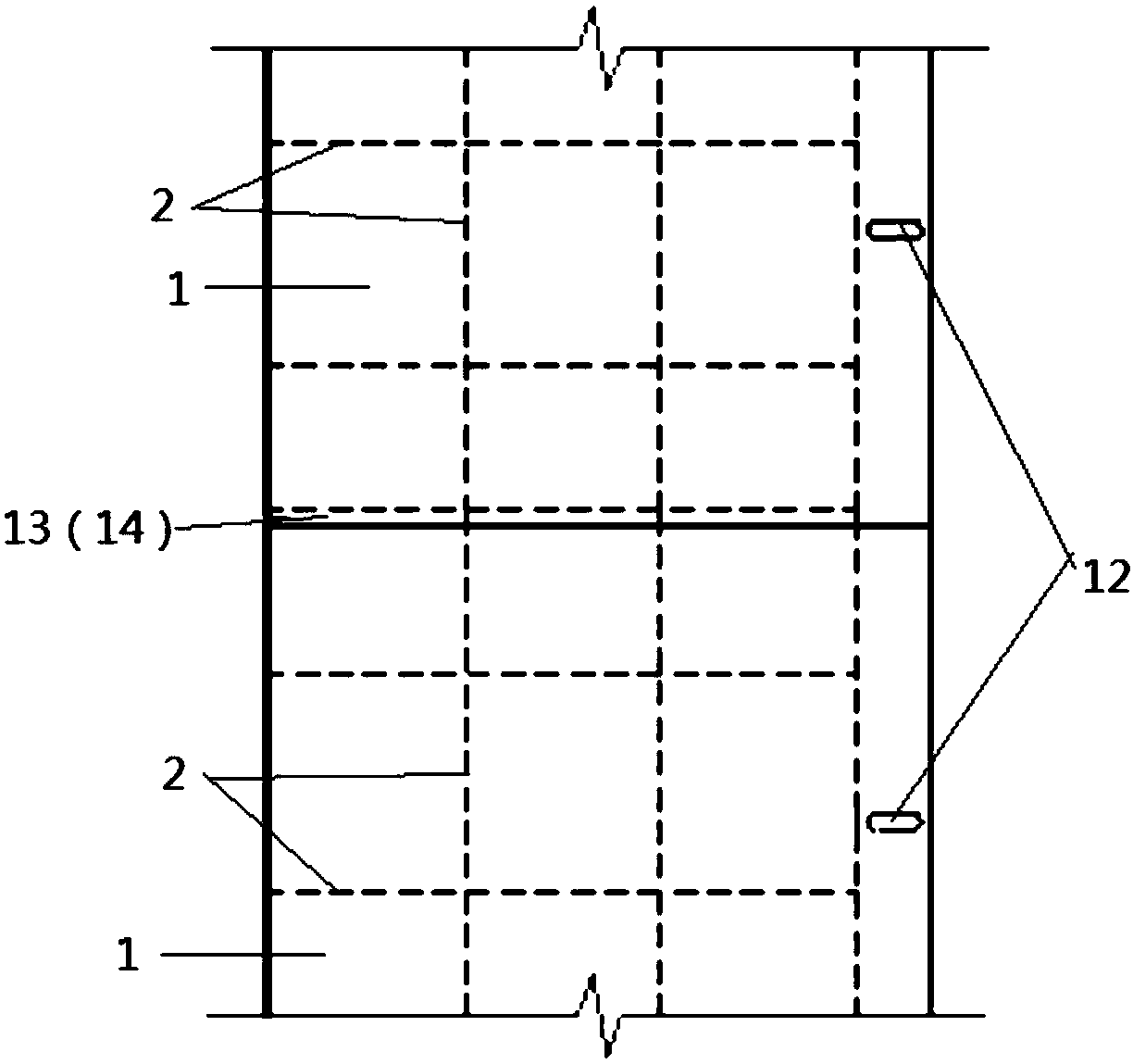
[0026] Such as figure 1 As shown, the telescopic steel formwork includes a rectangular panel 1 and stiffeners 2 fixedly arranged on the panel 1 , the stiffeners 2 are arranged to increase the rigidity of the panel 1 . The panel 1 in this embodiment is a steel plate. One of the two long sides of the panel 1 is provided with a telescopic adjustment side 11 of a certain width, and two long holes parallel to the short side of the panel are provided on the telescopic adjustment side 11 and are provided with pull bolts. 12. One of the two broad sides of the panel 1 is provided with a socket slot 13 , and the other of the two broad sides of the panel is provided with a socket key 14 .

[0027] In order to increase the rigidity of the panel, the stiffeners 2 are distributed on the outer side of the panel 1 in a criss-cross pattern, and the stiffeners 2 are n...


PUM


Abstract

The invention provides a stretchable steel formwork. The stretchable steel formwork is particularly suitable for construction of a construction concrete formwork with the circular variable cross section. The stretchable steel formwork is roughly rectangular, and comprises a face plate and stiffening ribs, and the stiffening ribs are distributed on the outer side of the face plate in a crisscross mode to enhance the rigidity of the face plate. The face plate is rectangular, a stretchable adjusting edge a certain distance away from the face plate is arranged on one long edge of the face plate, and long-strip holes parallel to the short edges of the face plate are formed in the stretchable adjusting edge. A socket key is arranged on one of the two short edges of the face plate, and a socket groove is formed in the other short edge of the face plate. When the stretchable steel formworks are subjected to annular lap joint, the adjacent stretchable steel formworks are fixed through split bolts, and the stretchable adjusting edges are located on the inner sides; as the long-strip holes are formed, the lap joint length of the two stretchable steel formworks is calculated and determined according to the change rate of the cross section of a circular building, and the appearance quality of concrete is improved; meanwhile, the stretchable steel formwork is high in standardization and suitable for industrial production, the construction progress can be improved, and therefore the construction cost can be reduced.

Description

technical field [0001] The invention belongs to the field of building construction, in particular to a telescopic steel formwork used for casting concrete for a circular variable-section building structure. Background technique [0002] In building construction, some buildings (structures) with circular variable cross-sections (hereinafter referred to as buildings) are often encountered. When constructing structural concrete formwork, the traditional method is to use a small number of wedge-shaped formwork to achieve circular cross-section changes. the goal of. However, the traditional wedge-shaped formwork can only be made by hand on site, the production process is complicated, and it is not suitable for mass production. Therefore, the production efficiency of the wedge-shaped formwork is low, and the construction site is occupied; the installation of the wedge-shaped formwork is also complicated. At the same time, the wedge-shaped formwork is not easy to be connected and ...

Claims


Application Information

Patent Timeline
Patent Type & Authority Patents(China)
IPC IPC(8): E04G11/04E04G9/08
CPCE04G9/083E04G11/04
Inventor 焦炳烨张连中
Owner CHINA HUAYE GROUP
Why Eureka
Try Eureka