A compressor assembly

A technology for compressors and compressor shells, which is applied in the field of compressors, and can solve problems such as unreliable operation or shutdown of compressors, rising discharge temperature of compressors, and increased workload, so as to reduce noise and reduce exhaust Temperature, the effect of reducing the pressure ratio of the whole machine

Active Publication Date: 2018-08-07
GREE ELECTRIC APPLIANCES INC
View PDF7 Cites 0 Cited by
  • Summary
  • Abstract
  • Description
  • Claims
  • Application Information

AI Technical Summary

Problems solved by technology

[0002] The rolling rotor compressors in the prior art are equipped with compressor liquid storage tanks in order to prevent liquid shock, so that the refrigerant entering the compressor chamber is all gas. In this solution, the compressor liquid storage tanks and shells are manufactured separately and then assembled 1. The liquid storage tank is often arranged outside the shell wall of the compressor shell, so that the center of gravity of the whole machine is not at the axial position of the compressor when the compressor assembly is assembled, which will cause the compressor to generate relatively large noise during operation; and the compressor The high-temperature heat of the compression chamber can only be taken away by the flowing air on the outer surface of the casing to cool down. Under high-temperature conditions, due to the increase in the workload, the discharge temperature of the compressor will increase, and the pressure ratio of the whole machine will increase, making the compressor unreliable. running or shutting down
[0003] Because the compressors in the prior art have technical problems such as high exhaust temperature, high pressure ratio of the whole machine and high noise, a new compressor assembly is designed in the present invention.

Method used


Image

  • A compressor assembly
  • A compressor assembly
  • A compressor assembly

Examples


specific Embodiment approach

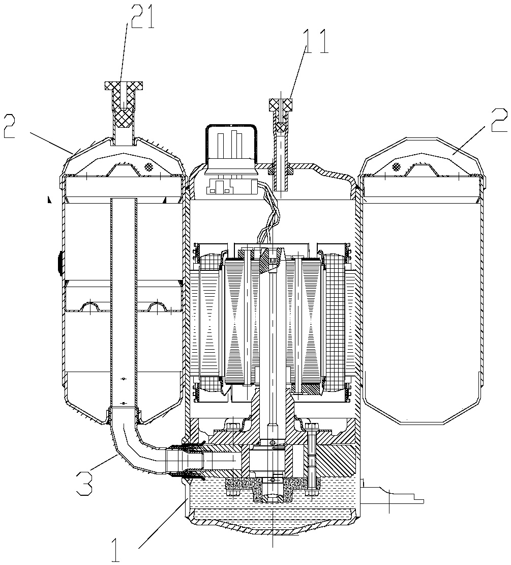
[0052] 1. The compressor assembly includes liquid storage tank 2, terminal, suction pipe 21, exhaust pipe 11, connecting pipe 3 and other parts;

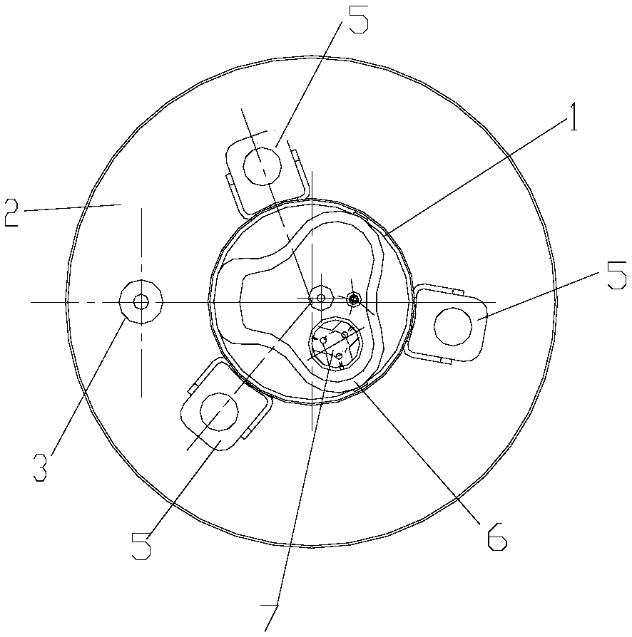
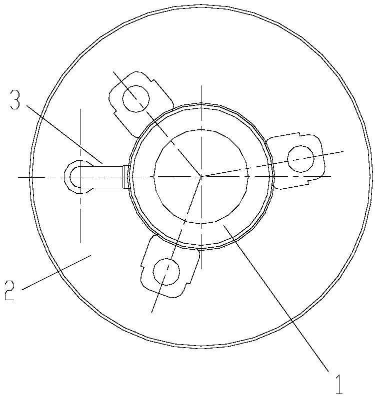
[0053] 2. If Figure 1-3 The shown compressor housing and liquid storage tank are designed as one piece, cast and molded; the liquid storage tank and compressor housing can also be non-cast, and the heat-conducting adhesive is used to seamlessly bond the two to the compressor housing;

[0054] 3. The compressor cavity is cylindrical, and the liquid storage tank and the compressor are integrated into a circular column shape. The upper end of the liquid storage tank has a suction pipe 21, and the lower end has a connecting pipe 3 connected to the suction port of the compressor cavity;

[0055] 4. The compressor liquid storage tank is designed as a concentric structure with the compressor cavity;

[0056] 5. The size of the compressor liquid storage tank can be designed with different radii according to the size of the system, but the...


PUM


Abstract

The invention provides a compressor assembly. The compressor assembly comprises a compressor shell (1) and a liquid storage tank (2). The compressor shell (1) is of a revolving body structure. An exhaust opening of the liquid storage tank (2) is connected to a sucking opening of the compressor shell (1). The surface of one side of the liquid storage tank (2) is attached to the outer surface of the compressor shell (1) and covers at least part of the peripheral outer surface of the compressor shell (1) of the revolving body structure. Through the compressor assembly, low-temperature refrigerant in the liquid storage tank can be effectively used for carrying out heat absorbing and cooling on the compressor shell and the inside of a compressor, so that the exhaust temperature of the compressor is effectively lowered. The refrigerant in the liquid storage tank can be heated through the high-temperature heat of the compressor shell to reach an overheated state, liquid impact is prevented, meanwhile, the pressure ratio of the whole compressor is lowered, and the operation energy efficiency of the compressor assembly is improved. Due to isolation of the liquid storage tank, outward transmission of motor noise during operation is reduced, the noise is lowered, and the operation quality of the whole compressor is improved.

Description

technical field [0001] The invention belongs to the technical field of compressors, and in particular relates to a compressor assembly. Background technique [0002] The rolling rotor compressors in the prior art are equipped with compressor liquid storage tanks in order to prevent liquid shock, so that the refrigerant entering the compressor chamber is all gas. In this solution, the compressor liquid storage tanks and shells are manufactured separately and then assembled 1. The liquid storage tank is often arranged outside the shell wall of the compressor shell, so that the center of gravity of the whole machine is not at the axial position of the compressor when the compressor assembly is assembled, which will cause the compressor to generate relatively large noise during operation; and the compressor The high-temperature heat of the compression chamber can only be taken away by the flowing air on the outer surface of the casing to cool down. Under high-temperature conditi...

Claims


Application Information

Patent Timeline
Patent Type & Authority Patents(China)
IPC IPC(8): F04C29/00F04C29/04F04C29/06
CPCF04C29/00F04C29/04F04C29/06F04C2240/30F04C2240/80
Inventor 罗永前彭光前廖敏熊军吴俊鸿
Owner GREE ELECTRIC APPLIANCES INC
Why Eureka
Try Eureka