Energy-saving waste water recycling and hot water constant-temperature supplying system

A technology of supply system and waste water recovery, applied in fluid heaters, lighting and heating equipment, etc., can solve the problems of easily damaged water meters, insufficient waste heat conversion, unreasonable structure, etc. Simple and good market competitiveness

Active Publication Date: 2016-12-07
广西天涌节能科技股份有限公司
View PDF7 Cites 0 Cited by
  • Summary
  • Abstract
  • Description
  • Claims
  • Application Information

AI Technical Summary

Problems solved by technology

[0005] The present invention aims at the defects of unreasonable structure, insufficient conversion of waste heat and easy damage of water meter in the existing waste heat recovery system, and provides an energy-saving waste water recovery hot water constant temperature supply system to solve the above problems

Method used


Image

  • Energy-saving waste water recycling and hot water constant-temperature supplying system
  • Energy-saving waste water recycling and hot water constant-temperature supplying system

Examples


Embodiment 1

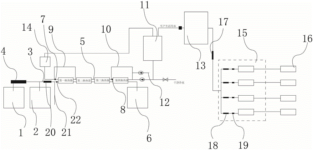
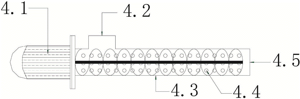
[0031] Such as figure 1 , Is a schematic diagram of the overall structure of the present invention, including the sewage tank 2, the sewage tank 2 is connected with the sewage pipe 3, the sewage pipe 3 is provided with a slag discharge device 4, the slag discharge device 4 includes a shell 4.3, on the shell 4.3 is provided Sewage inlet 4.2 and sewage hole 4.4. Sewage enters the housing 4.3 through the sewage inlet 4.2, and discharges the debris through the rotating mechanism in the housing 4.3 (driven by the motor 4.1), and the sewage continues in the sewage pipe through the sewage hole 4.4 3 flow, the system includes the first heat exchanger, the second heat exchanger, the third heat exchanger and the fourth heat exchanger, which are arranged in order from left to right. In the above heat exchanger, the sewage pipe 3 Connected to the heat exchanger in turn from left to right; on the right side is provided with a cold water pipe 5, which is connected to the heat exchanger in tur...

Embodiment 2

[0041] The difference from Embodiment 1 is that the first heat exchanger is provided with a water supplement pipe, and the remaining working modes and principles are the same as Embodiment 1.

Embodiment 3

[0043] Different from Example 1, when the system is installed in a school, the dormitory is vertical for each unit, and the water meters of each dormitory in the unit are collectively set in a box, and each water meter is connected to the card reader separately through a wire. The placement avoids the problem that students can destroy the water meter in the dormitory and abuse hot water at will. The structure is simple and convenient, and the setting of the water meter and the card reader can be realized according to the existing technology, and will not be described here.


PUM


Abstract

The invention discloses an energy-saving waste water recycling and hot water constant-temperature supplying system. The energy-saving waste water recycling and hot water constant-temperature supplying system comprises a sewage pool and a sewage pipe connected with the sewage pool. A multi-stage heat exchanger used for heat exchange is arranged in the sewage pipe. The energy-saving waste water recycling and hot water constant-temperature supplying system is characterized in that the system further comprises a cold water pipeline; after the cold water pipeline passes through the multi-stage heat exchanger for water temperature exchange, one end of the cold water pipeline is connected with the top of a heat preservation water tank, and the bottom of the heat preservation water tank is connected with the other end of the cold water pipeline; the heat preservation water tank is connected with a heat supply pump which is provided with a heating device; a plurality of water meters are connected to the rear portion of the heat supply pump, and each water meter is connected with a card reader and a water outlet; a water pipe for connecting the heat supply pump and the water meters is provided with a general control valve, and a branch control valve is arranged in the position of each water meter; and the sewage pipe is provided with a general sewage pipe body, a sewage valve and a flushing pipe.

Description

Technical field [0001] The invention relates to the field of energy regeneration and recovery, in particular to an energy-saving waste water recovery hot water constant temperature supply system. Background technique [0002] The water source heat pump hot water system is composed of a water source heat pump hot water host installed independently by each household and a public water source exchange source. Among them, the household water source heat pump hot water main engine is distributed and installed in each household to realize all the functions of independent start and stop and independent control of hot water temperature. Public water source exchange, the exchange water source temperature is low to avoid the loss of heat in the pipeline circulation, and save the use cost compared with the centralized hot water supply. Its working principle is to use the original sewage generated by the house itself, use the waste heat of the original sewage, use the regenerative energy ex...

Claims


Application Information

Patent Timeline
Patent Type & Authority Applications(China)
IPC IPC(8): F24H4/04F24H9/18F24H9/20F24H9/00
CPCF24H4/04F24H9/0005F24H9/1809F24H9/2007
Inventor 黄伟军梁华易刘永丽覃鐶何燕韦媛元梁锋华盘英靖赵代龙莫文贵
Owner 广西天涌节能科技股份有限公司
Why Eureka
Try Eureka