Automatic electrical drying chamber

An electrical automation, drying room technology, applied in drying, drying machine, non-progressive drying machine and other directions, can solve the problems of inability to realize electrical automatic drying, increase labor costs, affect work efficiency, etc., and achieve compact structure. , high energy-saving rate, the effect of improving thermal efficiency

Inactive Publication Date: 2016-12-07
LIAONING INST OF SCI & TECH
View PDF9 Cites 4 Cited by
  • Summary
  • Abstract
  • Description
  • Claims
  • Application Information

AI Technical Summary

Problems solved by technology

[0002] In some food or waste processing processes, it is often necessary to dry wet materials. Some existing dryers have simple structures and cannot achieve automatic electrical and mechanized drying. In the drying process, especially the drying of waste During the dry treatment process, the environmental pollution problem has not been solved, and multiple operators need to be equipped to coordinate the work, which not only affects the work efficiency, but also increases the labor cost

Method used


Image

  • Automatic electrical drying chamber
  • Automatic electrical drying chamber
  • Automatic electrical drying chamber

Examples


Embodiment Construction

[0020] In order to make the present invention be further understood, the present invention will be further described below with reference to accompanying drawing and specific embodiment of description:

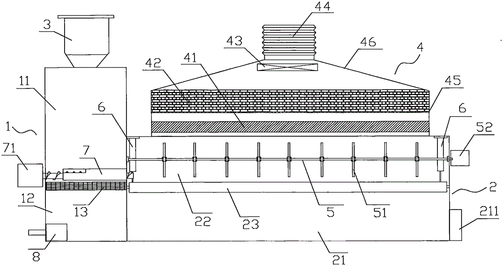
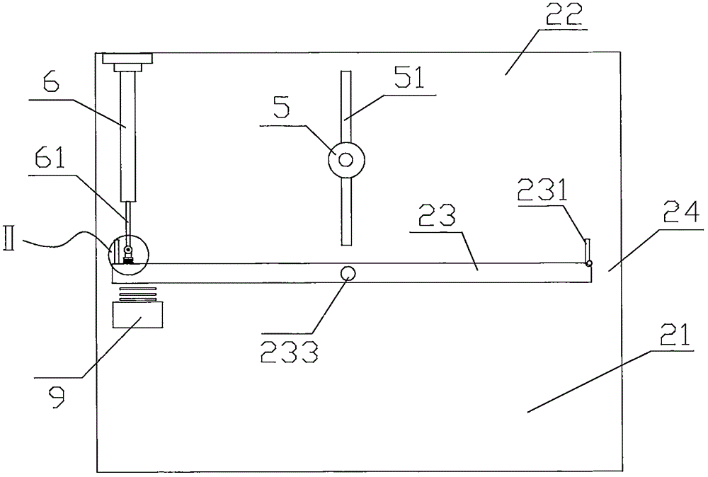
[0021] Such as Figure 1 to Figure 3 Shown, a kind of electrical automatic drying chamber, comprises drying chamber 2, is connected to the feed chamber 1 on one side of drying chamber 2 and is located at the deodorizing chamber 4 that is arranged on the top of drying chamber 2 and communicates with drying chamber 2, and feed chamber The top of 1 is provided with feed hopper 3. Wherein, as an improvement of the present invention, a flat high-frequency electromagnetic drying plate 23 is provided in the drying chamber 2, and the high-frequency electromagnetic drying plate 23 is rotatably connected in the drying chamber 2 through a rotating shaft 233, and its power is 40KW . The high-frequency electromagnetic drying plate 23 divides the chamber of the drying chamber 2 into an up...


PUM


Abstract

The invention discloses an automatic electrical drying chamber. The automatic electrical drying chamber comprises a drying room, a feeding chamber connected to one side of the drying room, and a deodorization chamber arranged on the top of the drying room and communicating with the drying room. A flat-plate-shaped high-frequency electromagnetic drying plate is arranged in the drying room. The high-frequency electromagnetic drying plate divides a cavity of the drying room into an upper evaporation cavity and a lower dry material storage cavity. A guide rod air cylinder is connected between the inner side edge of the high-frequency electromagnetic drying plate and the room roof of the drying room. A high-frequency vibration device is arranged below the inner side edge of the high-frequency electromagnetic drying plate. A buffering device is arranged between a guide rod of the guide rod air cylinder and the plate face of the high-frequency electromagnetic drying plate. The tail end of the guide rod is rotationally connected with the buffering device. A water filtering plate is arranged in the feeding chamber, and the feeding chamber is divided into an upper wet material storage cavity and a lower dirt water storage cavity. A spiral feeding rod is arranged at the position, close to the upper end face of the water filtering plate, of the wet material storage cavity, and a deodorization plate and a water absorbing plate are arranged in the deodorization chamber. The drying chamber is compact in structure and high in drying efficiency.

Description

technical field [0001] The invention relates to the technical field of material processing, in particular to an electric automatic drying chamber which dries quickly and can reduce environmental pollution. Background technique [0002] In some food or waste processing processes, it is often necessary to dry wet materials. Some existing dryers have simple structures and cannot achieve automatic electrical and mechanized drying. In the drying process, especially the drying of waste During the dry treatment process, the environmental pollution problem has not been solved, and multiple operators need to be equipped to coordinate the work, which not only affects the work efficiency, but also increases the labor cost. Contents of the invention [0003] In order to solve the defects of the above-mentioned technologies, the present invention provides an electric and automatic drying room that dries quickly and can reduce environmental pollution. [0004] The technical scheme adop...

Claims


Application Information

Patent Timeline
Patent Type & Authority Applications(China)
IPC IPC(8): F26B11/16F26B23/04C09D201/00C09D5/08C09D5/18C09D7/12
CPCF26B11/16C08K3/2279C08K3/36C08K5/03C08K13/02C08K2201/011C09D5/08C09D5/18C09D7/61C09D201/00F26B23/04
Inventor 孙振龙
Owner LIAONING INST OF SCI & TECH
Why Eureka
Try Eureka