Rectangular workpiece position and angle measurement method

A technology of angle measurement and workpiece position, applied in measurement devices, optical devices, instruments, etc., can solve the problems of complex system structure, high cost, interference of measurement accuracy, etc., to achieve simple measurement process, save fixture costs, and reduce positioning accuracy. desired effect

Active Publication Date: 2016-12-07
BAOSHAN IRON & STEEL CO LTD
View PDF11 Cites 17 Cited by
  • Summary
  • Abstract
  • Description
  • Claims
  • Application Information

AI Technical Summary

Problems solved by technology

But the disadvantage is that the measurement accuracy is easily disturbed by lighting and other conditions, and the installation conditions of the camera and light source are required. The system structure is more complicated and the cost is higher.

Method used


Image

  • Rectangular workpiece position and angle measurement method
  • Rectangular workpiece position and angle measurement method
  • Rectangular workpiece position and angle measurement method

Examples


Embodiment Construction

[0027] Below in conjunction with specific embodiment, further illustrate the present invention. It should be understood that these examples are only used to illustrate the present invention and are not intended to limit the scope of the present invention. In addition, it should be understood that after reading the content of the present invention, those skilled in the art may make various changes or modifications to the present invention, and these equivalent forms also fall within the scope defined by the appended claims of the present application.

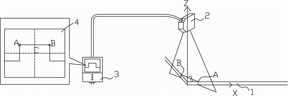
[0028] like figure 1 As shown, the rectangular sheet 1 is placed on the cutting platform, and the probe 2 of the two-dimensional shape measuring sensor is installed above it, which can move with the laser cutting head in the X or Y axis direction within the cutting range. The probe 2 is installed so that the linear light forms an angle θ—45° with the X-axis direction. The probe 2 emits a laser with a certain width to irradiate ...


PUM


Abstract

The invention discloses a rectangular workpiece position and angle measurement method, and the method comprises the steps: 1), enabling a two-dimensional shape measurement sensor to make plane movement in an X-axis or Y-axis direction in a cutting range along with a laser cutting head, enabling the light of a sensor to vertically irradiate an edge part of a steel plate in a downward manner, enabling the light to form an inclined angle theta with the X-axis direction, and obtaining the contour of the edge of the steel plate; 2), obtaining the left and right edge position values of a rectangular piece material through the first measurement; 3), carrying out the translational scanning measurement of the long side of the rectangular piece material, carrying out the sampling of the position of the long edge of the rectangular piece material, and recording the coordinate position of a machine tool; 4), employing a long edge data ample and a two-point straight line method or a least square method for the fitting of a straight line, and calculating the deflection angle of the long side of the rectangular piece material and the X-axis; 5), comparing a left and right edge value and a theoretical left and right edge value, and deducing the X-axis and Y-axis offsets of the rectangular piece material; 6), enabling the obtained deflection angle and the X-axis and Y-axis offsets to be transmitted to a numerical control system for the compensation of a workpiece coordinate system; 7), enabling the numerical control system to start to laser cutting through employing the workpiece coordinate system after compensation.

Description

technical field [0001] The invention belongs to the field of industrial measurement, and in particular relates to a method for measuring the position and angle of a rectangular workpiece, which is suitable for non-contact measurement of the position and angle of a large-sized rectangular workpiece. Background technique [0002] In the field of machine tool cutting, when laser cutting large-sized thin steel plates, the workpiece placed on the cutting platform must be positioned so that the workpiece is in the correct position relative to the machine tool and the laser cutting head, especially the edge of the workpiece. When it is used as the edge of the finished part, the positioning accuracy of the workpiece is required to be high, otherwise it will lead to dimensional errors of the cut part. [0003] The traditional method of workpiece positioning is to use mechanical fixtures to clamp the workpiece, and adjust it with the dial indicator and the marking method to make the p...

Claims


Application Information

Patent Timeline
Patent Type & Authority Applications(China)
IPC IPC(8): G01B11/00G01B11/26
Inventor 潘胜波金成国黄天茂梁兆东
Owner BAOSHAN IRON & STEEL CO LTD
Why Eureka
Try Eureka