Infrared thermal image detection device

A detection equipment and infrared thermal imaging technology, which is applied in the research field of infrared detectors, can solve the problems of potential safety hazards, slow preheating speed, poor efficiency, etc., and achieve good preheating effect, fast preheating speed and good effect

Inactive Publication Date: 2016-12-07
CHENGDU HANKANG INFORMATION IND
View PDF0 Cites 0 Cited by
  • Summary
  • Abstract
  • Description
  • Claims
  • Application Information

AI Technical Summary

Problems solved by technology

[0009] The invention provides an infrared thermal image detection device, which solves the technical problems that the existing infrared thermal imager has potential safety hazards when detecting power equipment, slow preheating speed, poor efficiency, and easy to be affected by moisture, and realizes a reasonable design of the equipment , high safety when testing electrical equipment, fast warm-up speed and good effect, and technical effect that is not easy to be affected by moisture

Method used


Image

  • Infrared thermal image detection device
  • Infrared thermal image detection device
  • Infrared thermal image detection device

Examples


Embodiment 1

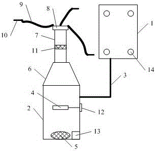
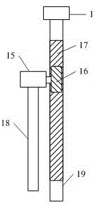
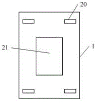
[0030] In Example 1, please refer to Figure 1-Figure 3 , providing an infrared thermal imaging detection device, the device comprising:

[0031] Infrared thermal imager 1, housing 2, first bracket 3, distance adjustment structure, wherein, the surface of the infrared thermal imager is evenly distributed with N preheating holes 14, and the preheating holes are provided with hole covers, and the infrared thermal imager The inner wall of the imager is provided with a drying layer, and the two ends of the first bracket are respectively threadedly connected with the infrared thermal imager and the shell; Open shape, the air inlet at the lower end of the gas collecting hood 6 is connected to the open end of the shell, the upper air outlet of the gas collecting hood is connected to one end of the exhaust main pipe 7, and the other end of the exhaust main pipe is connected to N exhaust pipes through the diverter valve 8. The gas branch pipe 9 is connected, and the other ends of the ...


PUM


Abstract

The invention discloses an infrared thermal image detection device. The device comprises an infrared thermal imager, a shell, a first support and a distance adjusting structure. N preheating holes are evenly formed in the surface of the infrared thermal imager. A dry layer is disposed on the inner wall of the infrared thermal imager, an electric heating bar is fixed in the middle in the shell, a fan is fixed to the bottom in the shell, an air inlet in the lower end of an air collecting cover is connected with the open end of the shell, an air outlet in the upper end of the air collecting cover is connected with one end of an exhaust main pipe, the other end of the exhaust main pipe is connected with N exhaust branch pipes through a flow divider, and the other ends of the N exhaust branch pipes are connected with N air needles respectively. The distance adjusting structure comprises a motor, a gear, a rack, a first rod and a second rod. The device has the advantages of being reasonable in design, high in safety during detection of power equipment, high in preheating speed, good in effect and not likely to be affected with damp.

Description

technical field [0001] The invention relates to the research field of infrared detectors, in particular to an infrared thermal image detection device. Background technique [0002] The infrared thermal imager uses the infrared detector and the optical imaging objective lens to receive the infrared radiation energy distribution pattern of the measured target and reflect it on the photosensitive element of the infrared detector to obtain an infrared thermal image, which is consistent with the thermal image on the surface of the object corresponding to the distribution field. In layman's terms, an infrared thermal imager converts the invisible infrared energy emitted by an object into a visible thermal image. Different colors on the top of the thermal image represent different temperatures of the measured object. [0003] Infrared thermal imaging cameras are often used in the detection of electrical equipment. Infrared imaging of electrical equipment can quickly detect electr...

Claims


Application Information

Patent Timeline
Patent Type & Authority Applications(China)
IPC IPC(8): G01J5/02G01J5/04B01L7/00
CPCG01J5/0205B01L7/00G01J5/048G01J2005/0077
Inventor 陈静柴军
Owner CHENGDU HANKANG INFORMATION IND
Why Eureka
Try Eureka