Method for measuring temperature through fiber core mismatching interference structure
A technology of interference structure and fiber core mismatch, which is applied in the field of optical communication and can solve problems such as limitations
- Summary
- Abstract
- Description
- Claims
- Application Information
AI Technical Summary
Problems solved by technology
Method used
Image

Examples
Embodiment Construction
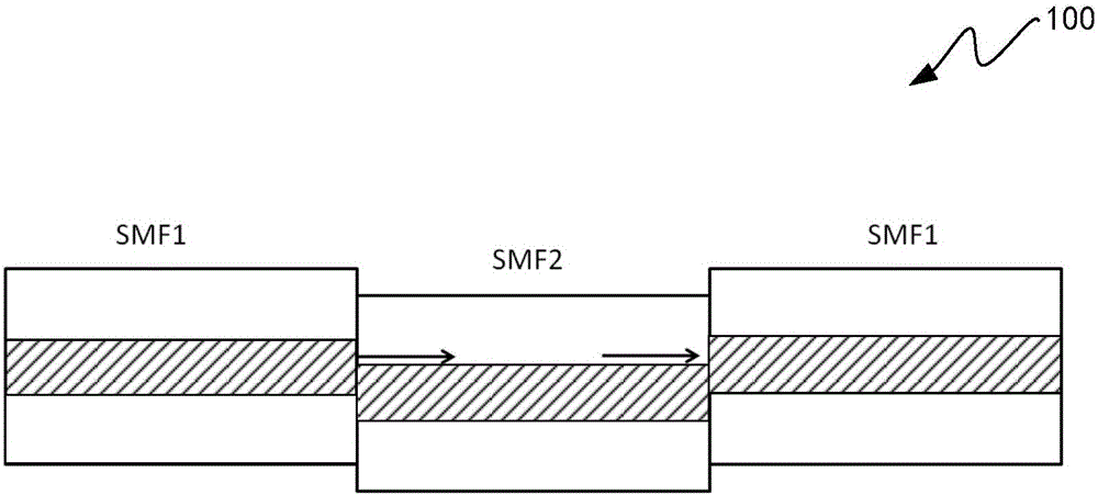
[0018] Core mismatch is the core mismatch during fiber splicing. According to the principle of core mismatch, the core mismatch interference structure is a special Mach-Zehnder interferometer. In the single mode-multimode-single mode (Single mode-Multi mode-Singlemode, SMS) structure (such as figure 1 As shown), the single-mode fiber at the input end couples the incident light into the single-mode fiber with dislocated core. After modulation by the multi-mode fiber, the incident light is led out through the single-mode fiber at the output end, and the light wave mode is transmitted along the optical fiber. In the transmission direction There will be a phenomenon that the light intensity changes periodically with the length of the multimode fiber, and even the light field distribution in the multimode fiber is almost the same as the incident light field. This is the mode interference effect in the multimode fiber, also called the mode Because the interference between multiple m...
PUM
| Property | Measurement | Unit |
|---|---|---|
| Length | aaaaa | aaaaa |
Abstract
Description
Claims
Application Information