
Differential Manchester decoding circuit and method

A decoding circuit and decoding method technology, applied in the field of differential Manchester decoding circuit, can solve the problems of high bit error rate and difficult to achieve accurate sampling clock

Active Publication Date: 2015-12-16
WUHAN RUINAJIE ELECTRONICS TECH
View PDF4 Cites 23 Cited by
  • Summary
  • Abstract
  • Description
  • Claims
  • Application Information

AI Technical Summary

Problems solved by technology

[0004] The embodiment of the present invention provides a differential Manchester decoding circuit and method, aiming to solve the existing need for a more accurate sampling clock for counting, so as to judge the length of the jump edge and recover the clock, but in the actual circuit system , an accurate sampling clock may be difficult to achieve, leading to problems with higher bit error rates

Method used


Image

  • Differential Manchester decoding circuit and method
  • Differential Manchester decoding circuit and method
  • Differential Manchester decoding circuit and method

Examples


Embodiment 1

[0047] figure 2A specific structural block diagram of the differential Manchester decoding circuit provided by Embodiment 1 of the present invention is shown, and for convenience of description, only parts related to the embodiment of the present invention are shown. In this embodiment, the circuit includes: a waveform conversion unit, a signal judgment unit, a data decoding unit and a signal filtering unit.

[0048] It should be noted that in wireless communication, differential Manchester coding is widely used due to its advantages of high efficiency and coupling clock coding information. Differential Manchester encoding is sent out after encoding. When the wireless receiving end receives the sent waveform, it is amplified by the amplifier and then quantized by the fixed level comparator to obtain the digital signal.

[0049] Wherein, the signal filtering unit is configured to perform average window filtering on the received digital signal to obtain the square wave signal...

Embodiment 2

[0067] Image 6 It shows the implementation flow of the differential Manchester decoding method provided by Embodiment 2 of the present invention, and the details are as follows:

[0068] Before step S601, the method also includes:

[0069] performing averaging window filtering on the received digital signal to obtain the square wave signal.

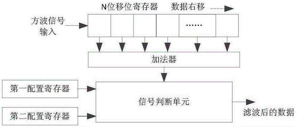
[0070] Specifically, input the received digital signal to an N-bit shift register, where N is a positive integer greater than or equal to 8;

[0071] summing each bit in the shift register through an adder;

[0072] Comparing the summation result with the first configuration register and the second configuration register, wherein, if the summation result is greater than or equal to the value of the first configuration register, the filtered data is 1, and if the summation If the result is less than or equal to the value of the second configuration register, the filtered data will be 0. In other cases, the filtered data will remain unc...


PUM


Abstract

The invention belongs to the technical field of wireless communications and provides a differential Manchester decoding circuit and method. The circuit comprises: a waveform conversion unit for sampling a received square wave signal to obtain a high level or a low level and performing computing operations of different types on a sampling counter to convert the square wave signal into a triangular wave signal; a signal judgment unit for judging the high and low levels of the triangular wave signal by use of a preset high level threshold and a preset low level threshold, respectively, and recovering decoding clock and intermediate data by judging the wave crests and the wave troughs of the triangular wave signal; and a data decoding unit for performing twice sampling on the intermediate data with the decoding click and performing EXCLUSIVE OR processing on the sampled data to obtain decoded data. The differential Manchester decoding circuit is capable of eliminating the influence of clock skew by virtue of self-addition and self-subtraction of the sampling counter, and is simple in circuit structure and low in error code occurrence rate.

Description

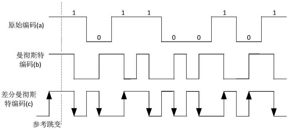
technical field [0001] The invention belongs to the technical field of wireless communication, and in particular relates to a differential Manchester decoding circuit and method. Background technique [0002] Manchester Encoding (Manchester Encoding, ME), also known as phase encoding, is a synchronous clock encoding technology commonly used in LAN transmission. Manchester coding is a coding method for synchronous transmission of data. There is a jump in the middle of each bit, jumping from low to high means 0, and jumping from high to low means 1; it can also be defined in the opposite way, jumping from low to high Change means 1, jumping from high to low means 0, and differential Manchester encoding has further improvement on the basis of Manchester encoding. In the code stream, the same direction as the previous jump is data 0, and the reverse is data 1. Such as figure 1 As shown, therefore, it is necessary to distinguish the long level and the short level in the receive...

Claims


Application Information

Patent Timeline
IPC IPC(8): H03M5/12
Inventor 陈毅成彭颖张明宇
Owner WUHAN RUINAJIE ELECTRONICS TECH
Learn More