A Cooler for Large Diameter Hypersonic Wind Tunnel

A hypersonic, cooler technology, used in the testing of instruments, machines/structural components, measuring devices, etc., can solve the problems of large volume, inability to block, and difficulty in transportation and installation, to ensure the flow area, Reduced pressure loss and easy procurement

Active Publication Date: 2018-08-17
中国空气动力研究与发展中心超高速空气动力研究所
View PDF6 Cites 0 Cited by
  • Summary
  • Abstract
  • Description
  • Claims
  • Application Information

AI Technical Summary

Problems solved by technology

[0004] In order to ensure the establishment of the large-diameter hypersonic wind tunnel flow field, the pressure loss of the wind tunnel air flow through the cooler should be small, which requires the cooler to have a sufficient flow area and the degree of blockage should not be large; the wind tunnel air flow reaches the cooler The temperature at the inlet can reach up to 830K, and the cooler is required to have a good heat exchange efficiency to ensure that the outlet temperature is not higher than 350K; when the cooler is working, it is in a negative pressure state for a long time and operates under vacuum, and the highest vacuum degree can reach 10Pa ; The hot air flow to be cooled in the wind tunnel is up to 320kg / s, and the cooling water flow is required to be no less than 745kg / s; due to the overall structure of the large-diameter hypersonic wind tunnel, the on-site installation of the cooler requires high-altitude operations, and the scale range of the cooler is 13 meters, 7.3 meters wide, and 6 meters high, the volume is huge, which significantly increases the difficulty of transportation and installation

Method used


Image

  • A Cooler for Large Diameter Hypersonic Wind Tunnel
  • A Cooler for Large Diameter Hypersonic Wind Tunnel
  • A Cooler for Large Diameter Hypersonic Wind Tunnel

Examples


Embodiment Construction

[0036] The present invention will be described in detail below in conjunction with the accompanying drawings.

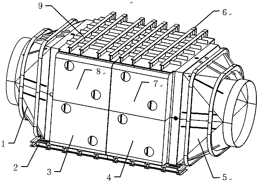
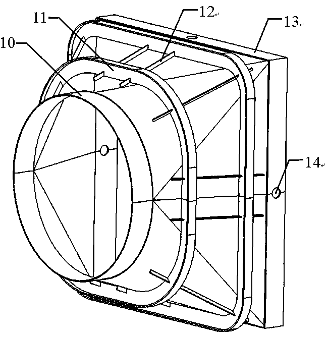
[0037] Such as figure 1As shown, the cooler for a large-diameter hypersonic wind tunnel includes a front transition section 1, a tube box, a base 2, a rear transition section 5, a side shell 6, and an upper shell 9; the tube box is placed on the base 2 , the upper surface of the pipe box is welded to the upper shell 9, the front end of the pipe box is welded to the transition section square interface 13 of the front transition section 1, the rear end of the pipe box is welded to the square interface of the rear transition section 5; the left side of the pipe box is fixed Water tank, the right side of the pipe box is an active water tank, the side shell 6 covers the outer surface of the active water tank and leaves a gap with the active water tank, and the side shell 6 and the upper shell 9 are welded at the joint;

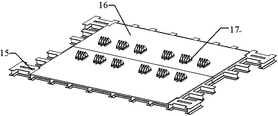
[0038] The pipe box is composed of an array of pip...


PUM


Abstract

The invention provides a cooler for a large-aperture hypersonic wind tunnel. A pedestal of the cooler is provided with a channel. The upper part of the channel is welded with an upper shell. The front end of the channel is welded with a square interface of a front transition segment. The rear end of the channel is welded with a square interface of a rear transition segment. The left side of the channel is a fixed water tank and the right side of the channel is a movable water tank. A side shell covers the outer surface of the movable water tank and reserves a gap with the movable water tank. The side shell and the upper shell are welded at a butt joint position. The channel is formed by combining channel modules of the same structure in arrays, and installation and welding are carried out by using a cordwood system stacking mode of from left to right and from bottom to top. Alternatively-arranged finned tubes are arranged between fixed water tank tube plates and movable water tank tube plates, and the finned tubes serve as heat exchange tubes to increase the heat exchange area. The cooler adopts a mode of a high temperature air flow and cooling water horizontally cross flow, and thus the heat exchange efficiency is raised. The cooler is advantaged by being compact in structure and high in heat exchange efficiency, and capable of meeting operation requirements of the large-aperture hypersonic wind tunnel.

Description

technical field [0001] The invention belongs to the field of hypersonic wind tunnel equipment construction, and in particular relates to an air cooler used in large-diameter hypersonic wind tunnel equipment. Background technique [0002] When a hypersonic wind tunnel operates at a Mach number above 5, in order to prevent condensation of the air flow, the high-pressure air needs to be heated by a heater before entering the front chamber of the wind tunnel. If the heated high-temperature air flows directly into the vacuum spherical tank after passing through the nozzle, test section, diffuser, and vacuum pipe, it will cause the pressure in the spherical tank to rise rapidly, so that the required pressure ratio is established in the wind tunnel flow field (front chamber The ratio of the total pressure to the pressure of the vacuum spherical tank) will soon reach a critical value, which will shorten the effective operation time of the wind tunnel. In order to eliminate this eff...

Claims


Application Information

Patent Timeline
Patent Type & Authority Patents(China)
IPC IPC(8): G01M9/04
CPCG01M9/04
Inventor 林敬周孙启志朱涛章起华孟祥润钟俊许晓斌曹程胡文东张绍武
Owner 中国空气动力研究与发展中心超高速空气动力研究所
Why Eureka
Try Eureka