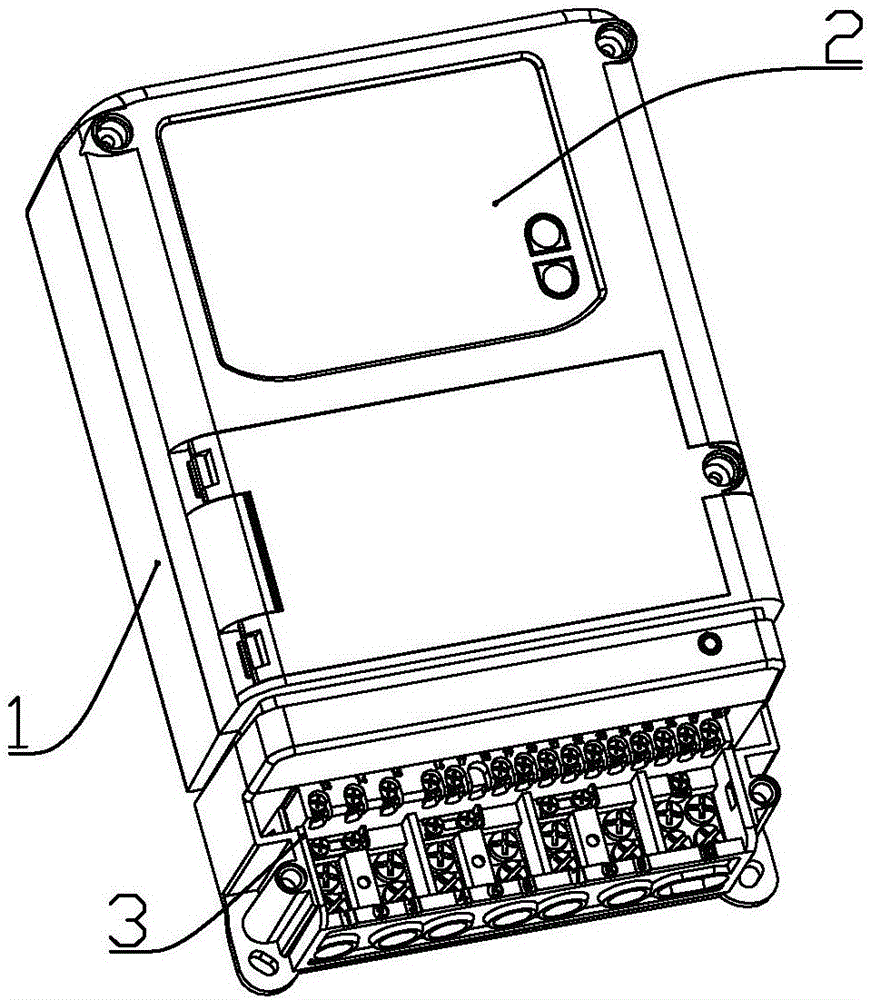
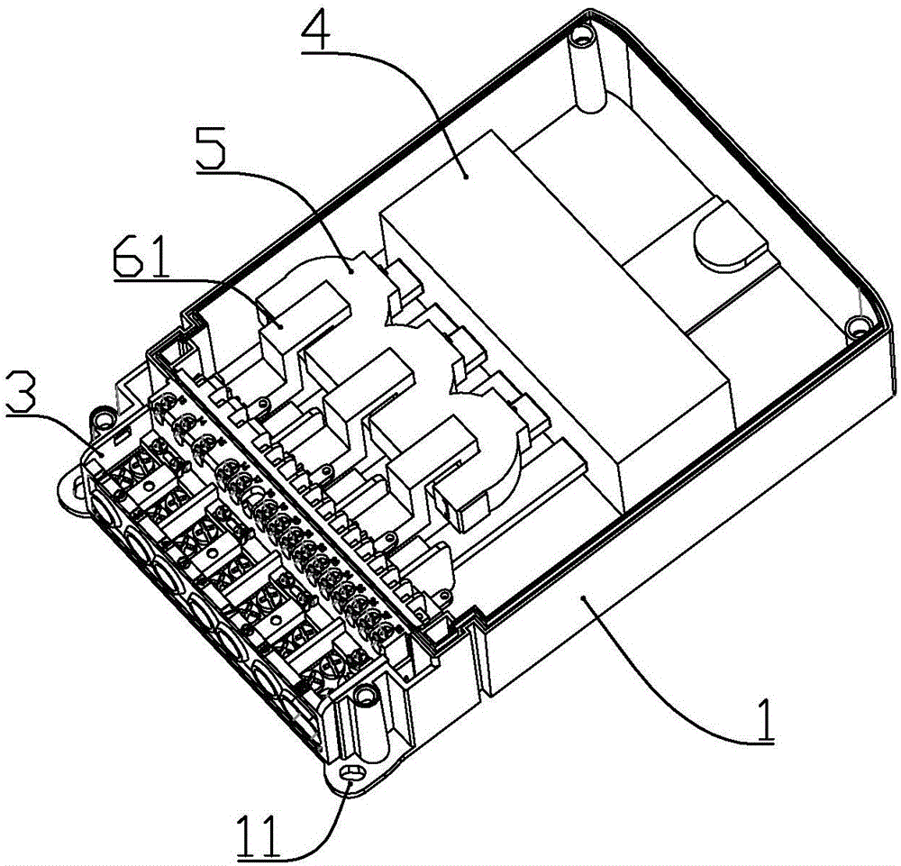
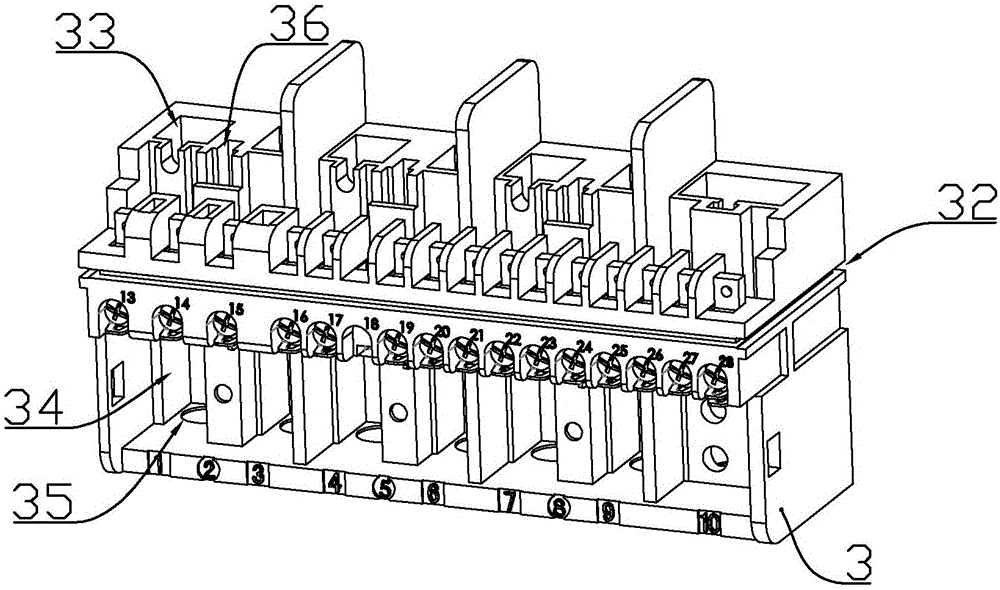
Three-phase electric meter

A three-phase electric meter and current terminal technology, applied in the electric power field, can solve the problems of shortening the service life of the smart electric meter, affecting the service life of the electric energy meter, large heat generation in the wiring slot, etc. Ensure the effect of normal sampling

Active Publication Date: 2016-12-07
ANTE METER GRP
View PDF7 Cites 0 Cited by
  • Summary
  • Abstract
  • Description
  • Claims
  • Application Information

AI Technical Summary

Problems solved by technology

[0003] However, when the electric wire is connected to the relay through the electromagnetic current transformer, there will be a connection node at the connection between the electric wire and the electromagnetic current transformer, which increases the resistance value at this place, causes an increase in heat generation, and shortens the above-mentioned intelligence. Service life of the meter
[0004] In addition, the general structure of the connection terminal at the lower part of the electric energy meter is to form a wire slot at the bottom of the connection terminal, and connect a screw on the front side of the connection terminal to clamp the wire in the wire slot, but because the diameter of the wire is always smaller than the wire plug The inner diameter of the groove, so that the outer wall of the wire and the inner wall of the wire slot form a line contact, and the front end of the screw and the outer wall of the wire are only in line contact, so the contact resistance between the wire and the wiring slot is large, and when the current is large, it will lead to wiring. The slot part generates a lot of heat, which accelerates the aging of the electric energy meter components and affects the overall service life of the electric energy meter

Method used


Image

  • Three-phase electric meter
  • Three-phase electric meter
  • Three-phase electric meter

Examples


Embodiment 2

[0074] combine Figure 16 and Figure 17 , this embodiment makes the following improvements on the basis of Embodiment 1: the locking screw b69 is formed with an internally threaded hole in the axial direction, and the internally threaded hole is a tapered hole with a wide front and a narrow rear. The thread is a left-handed thread, and the thread on the outer wall of the locking screw b is a right-handed thread; the locking screw b is provided with 4 strip-shaped gaps equidistant along the circumference, and the strip-shaped gaps extend from the bottom of the nut of the locking screw b To the front end of the locking screw b; the internal thread of the internal threaded hole is connected with a tapered screw 691 with a wide front and a narrow rear, and the outer wall of the tapered screw is correspondingly formed with a left-handed thread.

[0075] The tapered screw is pre-connected to the locking screw b. When in use, connect the locking screw b to the screw hole a. After t...


PUM


Abstract

The invention discloses a three-phase electric meter. The three-phase electric meter comprises a lower shell, an upper shell connected to the lower shell, a wire holder and a relay and mutual inductors which are installed in the lower shell; terminal sockets and a voltage terminal slot are formed in the upper end face of the wire holder; three groups of current terminals and a zero terminals are sequentially inserted into each terminal socket of the wire holder from left to right; each group of the current terminals comprise the first current terminal and the second current terminal; the first current terminal and the second current terminal of each group of the current terminals are connected with the relay separately; each mutual inductor comprises a main body portion and an inserting portion; the mutual inductors are installed at the inner connecting ends of the corresponding first current terminals, and installing portions of the mutual inductors are located in penetrating holes formed by U-shaped openings and the inserting portions; the mutual inductors can be disassembled, therefore, first wire outgoing terminals are directly connected with the relay, no redundant connecting node exists, parts of resistance values of the first wire outgoing terminals are decreased, the heating amount is decreased, and the service life of the electric meter is prolonged.

Description

technical field [0001] The invention belongs to the technical field of electric power, in particular to a three-phase electric meter. Background technique [0002] The Chinese Utility Model Patent No. 201320236205.0 proposes a smart meter with an electromagnetic current transformer with antimagnetic structure; the smart meter includes a meter base, a relay, an electromagnetic current transformer, terminal blocks and a primary current transformer. conductor; the electromagnetic current transformer has an annular iron core; the above-mentioned smart meter adopts the axis of the annular iron core of the electromagnetic current transformer to be set perpendicular to the bottom plane of the electric meter base, so that the first iron core of the transformer, the second The magnetic field generated by the second iron core during one pass is perpendicular to the magnetic field generated by the magnet at the bottom of the electric energy meter, and the magnetic field generated by th...

Claims


Application Information

Patent Timeline
Patent Type & Authority Applications(China)
IPC IPC(8): G01R11/00G01R11/02
CPCG01R11/00G01R11/02
Inventor 王月园
Owner ANTE METER GRP
Why Eureka
Try Eureka