
Phase test device

A technology for testing devices and phases, applied to measuring devices, the phase angle between voltage and current, and measuring electrical variables, etc., can solve the problems of costing a lot of money, manpower and material resources, and achieve the effect of saving labor and cost

Active Publication Date: 2016-12-07
FUJIAN NINGDE NUCLEAR POWER
View PDF6 Cites 3 Cited by
  • Summary
  • Abstract
  • Description
  • Claims
  • Application Information

AI Technical Summary

Problems solved by technology

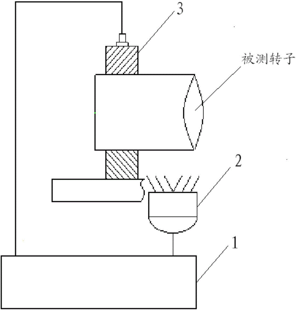
[0003] The object of the present invention is to provide a phase test device to solve the problem that in the prior art, when measuring the phase of the rotating device under test in operation, it is necessary to stop the operation of the rotating device under test first, so that the test process requires a lot of time. Financial, human and material resources

Method used


Image

  • Phase test device
  • Phase test device

Examples


Embodiment Construction

[0044] The following will clearly and completely describe the technical solutions in the embodiments of the present invention with reference to the accompanying drawings in the embodiments of the present invention. Obviously, the described embodiments are only some, not all, embodiments of the present invention. Based on the embodiments of the present invention, all other embodiments obtained by persons of ordinary skill in the art without creative efforts fall within the protection scope of the present invention.

[0045] A stroboscope is an optical measuring instrument that controls the light source to flash quickly at a specific frequency. The stroboscope can emit short and frequent flashes. When the flash frequency is close to or synchronized with the rotation or movement speed of the measured object, the surface quality or movement of the high-speed moving object can be easily observed by using the eye's persistence of vision or video synchronization. situation.

[0046]...


PUM


Abstract

An embodiment of the invention discloses a phase test device. The device comprises a vibration sensor data collector, a stroboscope and a vibration sensor. A first input terminal of the vibration sensor data collector is connected to an output terminal of the stroboscope and a second input terminal is connected to an output terminal of the vibration sensor. The stroboscope is used for outputting a key phase signal whose rotation frequency is the same with a rotation frequency of a detected rotation device to the vibration sensor data collector. The vibration sensor is used for detecting and outputting a vibration sensor signal of the detected rotation device to the vibration sensor data collector. When the above scheme is used to detect a phase of the detected rotation device which is operated, the operation of the detected rotation device does not need to be stopped and a sign position of the detected rotation device can be checked; and through the vibration sensor data collector, a vibration high point phase of the detected rotation device and a phase of the sign position can be measured. A whole process is time-saving and labor-saving and cost is low.

Description

technical field [0001] The present invention relates to the technical field of rotating machinery dynamic balancer system, and more specifically, relates to a double frequency phase test device. Background technique [0002] In the vibration analysis of rotating machinery, phase has its special meaning. It refers to the phase difference between the vibration signal and a mark on the shaft. Whenever the mark on the rotating shaft rotates to the key phase vibration sensor, a pulse signal will be generated. The phase is defined as the phase difference between the reference pulse signal and a certain point (such as positive peak or zero point, etc.) on the vibration signal. At present, the relatively common phase definition at home and abroad is the angle from the leading edge of the standard pulse signal to the first positive peak value of the previous vibration signal, that is, the pulse signal is in front and the positive peak value of the vibration signal is behind. At pr...

Claims


Application Information

Patent Timeline
Patent Type & Authority Applications(China)
IPC IPC(8): G01R25/00
Inventor 杨璋王维友李如源
Owner FUJIAN NINGDE NUCLEAR POWER
Learn More