Fault detection equipment and fault detection method

A fault detection and equipment technology, applied in the direction of digital circuit testing, electronic circuit testing, etc., can solve problems such as the complexity of the fault detection process of digital processing modules, and achieve the effects of simplifying complexity, simplifying the operation process, and solving complexity

Active Publication Date: 2016-12-07
SICHUAN JIUZHOU ELECTRIC GROUP
View PDF5 Cites 6 Cited by
  • Summary
  • Abstract
  • Description
  • Claims
  • Application Information

AI Technical Summary

Problems solved by technology

[0005] Embodiments of the present invention provide a fault detection device and a fault detection method, which are used to solve the technical problem that the fault detection process of th

Method used


Image

  • Fault detection equipment and fault detection method
  • Fault detection equipment and fault detection method
  • Fault detection equipment and fault detection method

Examples


Embodiment 1

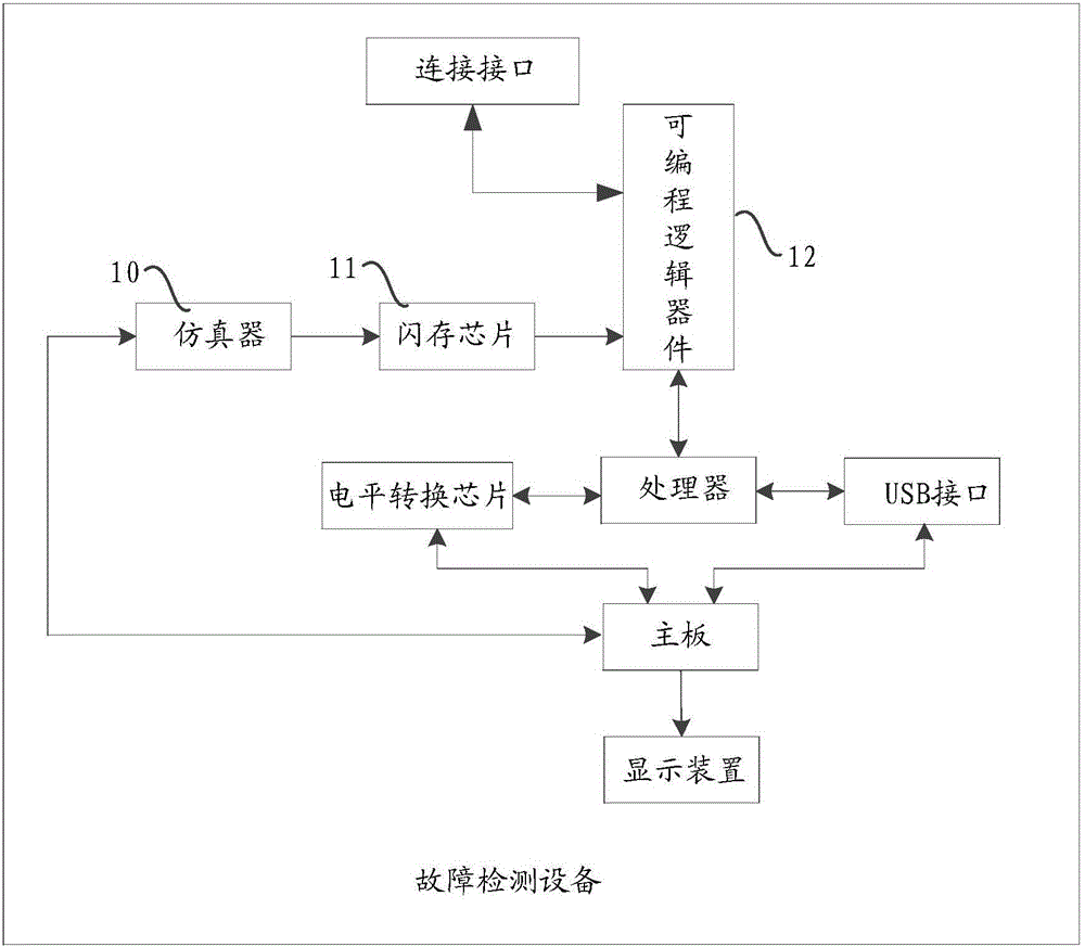
[0057] Please refer to figure 1 , Embodiment 1 of the present application provides a fault detection device, including:

[0058] Emulator 10, for downloading the first test program;

[0059] A flash memory chip 11, connected to the emulator 10, for storing the first test program;

[0060] A programmable logic device 12 is connected to the flash memory chip 11;

[0061] Wherein, when the fault detection device is connected with a digital processing device, the fault detection device reads and runs the first test program from the flash memory chip through the programmable logic device to determine the digital Whether the processing device is faulty.

[0062] In the embodiment of the present application, the emulator is connected between the motherboard and the flash memory chip, and the emulator may specifically be a BMD emulator or a JTAG emulator. In the specific implementation process, if the emulator takes a JTAG emulator as an example, the JTAG emulator and the motherbo...

Embodiment 2

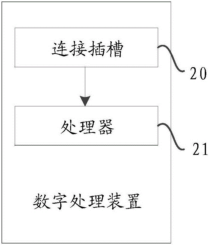
[0117] Please refer to figure 2 , a digital processing device is provided in an embodiment of the present application, including:

[0118] Connection slot 20 for connecting with fault detection equipment;

[0119] Processor 21, connected to the connection slot;

[0120] Wherein, when the digital processing device is connected to the fault detection device through the connection slot, download and run the first test program, and sequentially control each input / output port on the connection interface corresponding to the connection slot The level value of the switch jumps according to the preset time interval.

[0121] In the embodiment of the present application, the digital processing device is specifically a processing device including an FPGA chip, a DSP processor, and a power supply chip, and in the embodiment of the present application, the chips in the digital processing device, such as: FPGA and DSP are packaged by BGA way of encapsulation.

[0122] Further, the dig...

Embodiment 3

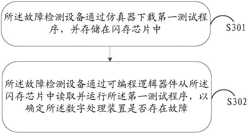
[0127] Please refer to image 3 , the embodiment of the present application provides a fault detection method applied to fault detection equipment, when the fault detection equipment is connected to a digital processing device, the method includes:

[0128] S301: The fault detection device downloads the first test program through the emulator, and stores it in the flash memory chip;

[0129] S302: The fault detection device reads and runs the first test program from the flash memory chip through a programmable logic device, acquires the pin working status of the pins of the digital processing device, and uses the The working status determines whether the digital processing device is faulty.

[0130] In the embodiment of the present application, step S301 is first performed: the fault detection device downloads the first test program through an emulator, and stores it in a flash memory chip.

[0131] In the embodiment of the present application, the emulator may specifically ...


PUM


Abstract

The invention discloses fault detection equipment and a fault detection method. The equipment comprises an emulator, a flash memory chip and a programmable logic device, wherein the emulator is used for downloading a first test program; the flash memory chip is connected to the emulator and is used for storing the first test program; and the programmable logic device is connected to the flash memory chip. When the fault detection equipment is connected to a digital processing device, the fault detection equipment reads and operates the first test program from the flash memory chip through the programmable logic device, and acquires a base pin work state of the digital processing device so as to determine whether the digital processing device has a fault according to the base pin work state. By using the technical scheme provided in the invention, a problem that a fault detection process of the digital processing device is complex in the prior art is solved.

Description

technical field [0001] The invention relates to the field of equipment fault detection, in particular to a fault detection device and a fault detection method. Background technique [0002] With the continuous development of science and technology, LSI, VLSI, ULSI have appeared one after another, the integration level of silicon single chip has been continuously improved, the requirements for integrated circuit packaging have become more stringent, the number of I / O pins has increased greatly, and power consumption has also increased. Large, in order to meet the needs of development, on the basis of the original packaging varieties, a new variety, ball grid array packaging, has been added. [0003] In the prior art, the fault detection method for chips packaged in ball grid arrays is to remove the chips and re-solder them one by one. If there are still faults, replace the devices one by one. However, taking and re-soldering the chips is a very complicated process. , At the ...

Claims


Application Information

Patent Timeline
IPC IPC(8): G01R31/317
Inventor 薛飞冷晓江
Owner SICHUAN JIUZHOU ELECTRIC GROUP
Why Eureka
Try Eureka