Fast response mixed signal generator and implementation method thereof
A mixed-signal, fast-response technology, used in digital function generators, instruments, electrical and digital data processing, etc., can solve the problems of increased waveform distortion of superimposed signals, and achieve less waveform data, fast response time, and easy program control. Effect
- Summary
- Abstract
- Description
- Claims
- Application Information
AI Technical Summary
Problems solved by technology
Method used
Image
Examples
Embodiment 1
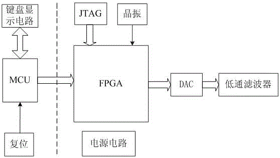
[0028] combine figure 1 The mixed signal generator with fast response in this embodiment includes an interface circuit, a single-chip microcomputer (MCU), a low-pass filter, an FPGA unit, and a DAC unit. A power supply circuit, a JTAG unit, a crystal oscillator unit and a DAC unit, and the DAC unit is electrically connected to a low-pass filter.
Embodiment approach
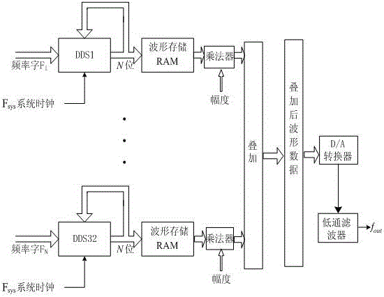
[0029] combine figure 2 , is the first preferred embodiment of the present invention, the mixed signal is formed by superposition of 28 sinusoidal components, 2 pulse components and 2 triangular components, a total of 32 components, and its waveform generation circuit consists of a single chip FPGA and an analog circuit composition. In the FPGA, the microprocessor sets all component parameters through the interface circuit. The FPGA selects the Cyclone III generation EP3C55F484C6 chip, the external crystal oscillator clock frequency is 40MHz, and the system clock Fsys is 400MHz after frequency multiplication by the phase-locked loop.
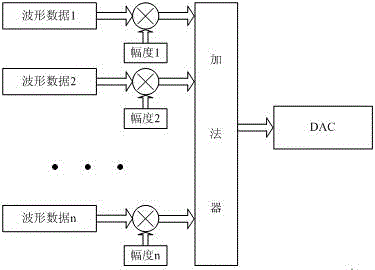
[0030] image 3 for figure 2 The topology structure diagram of the data synthesis in the data synthesis part, the data synthesis of the entire waveform amplitude is completed inside the FPGA. Multiple waveform data pass through the multiplier first, and then pass through the adder together. This process completes the synthesis of the wavefo...
Embodiment 2
[0036] combine Figure 7 , is the second preferred implementation mode of the present invention, and its working principle is the same as that of the first implementation mode, except that the parameters of components used and the technical indicators of function signals are different.
[0037] exist Figure 7 Among them, the arbitrary waveform signal with 8 components of the mixed signal, according to the Fourier principle, any signal can be represented by a sinusoidal signal, that is, there are 8 sinusoidal components in total. The programmable logic device FPGA uses Cyclone IV generation EP4CE115F29C7N, and Fsys is the frequency of the external crystal oscillator 50MHz, the system clock Fsys is 300MHz after frequency multiplication by phase-locked loop.
[0038] Figure 7 In the shown control logic unit, the amplitude word is 12bit, the frequency word is 32Bit, the phase word is 12Bit, and the pulse width word is 12Bit. The amplitude resolution is 0.1%, the frequency res...
PUM
 Abstract
Description
Claims
Application Information
 - R&D
- Intellectual Property
- Life Sciences
- Materials
- Tech Scout
- Unparalleled Data Quality
- Higher Quality Content
- 60% Fewer Hallucinations
Browse by: Latest US Patents, China's latest patents, Technical Efficacy Thesaurus, Application Domain, Technology Topic, Popular Technical Reports.
© 2025 PatSnap. All rights reserved.Legal|Privacy policy|Modern Slavery Act Transparency Statement|Sitemap|About US| Contact US: help@patsnap.com


