Image distortion method based on matrix inverse operation in virtual reality (VR) mobile end
What is AI technical title?
AI technical title is built by PatSnap AI team. It summarizes the technical point description of the patent document.
A technology of virtual reality and image distortion, applied in the field of virtual reality
Active Publication Date: 2016-12-07
NANJING RUIYUE INFORMATION TECH
View PDF4 Cites 6 Cited by
Summary
Abstract
Description
Claims
Application Information
AI Technical Summary
This helps you quickly interpret patents by identifying the three key elements:
Problems solved by technology
Method used
Benefits of technology
Problems solved by technology
[0006] Purpose of the invention: The technical problem to be solved by the present invention is to generate an intermediate frame for insertion when a frame cannot be rendered within the specified time in a virtual reality game, so as to reduce the screen shake in the game
Method used
Image
Click on the blue label to locate the original text in one second.
Reading with bidirectional positioning of images and text.
Examples
Embodiment 1
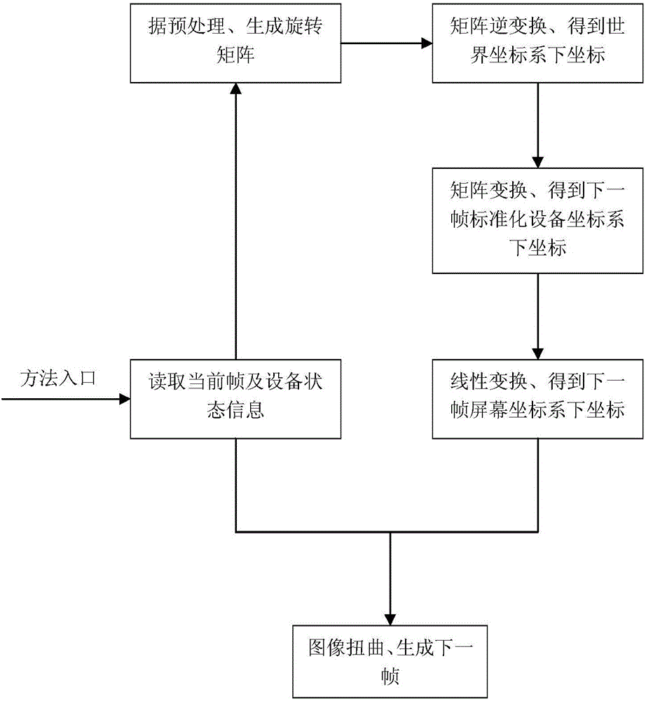
[0057] Embodiment 1: an image warping method based on matrix inverse operation in a virtual reality mobile terminal, comprising the following steps:
[0058] Step 1, read the current frame information, and get the coordinates in the screen coordinate system at the current frame moment (x original ,y original ) T , read the status of the current frame and the next frame of the device;
[0059] Step 2, perform necessary preprocessing on the read-in data in step 1, and set the coordinates (x original ,y original ) T Convert to coordinates (x, y, z, w) in the standardized device coordinate system at the current frame time T , generate the first rotation matrix R and the second rotation matrix R' according to the device state;
[0060] Step 3, according to the projection matrix P, the first rotation matrix R, and the viewpoint translation matrix T, standardize the coordinates (x, y, z, w) in the device coordinate system for each current frame moment T Perform matrix inverse ...
Embodiment 2
[0068] Embodiment 2: As described in Embodiment 1, a method for image warping based on matrix inverse operation in a virtual reality mobile terminal, step 1 includes:
[0069]Before the image is about to be displayed on the screen device, read the current frame information, that is, the framebuffer content, including the colorbuffer and depthbuffer content that has been rendered into a texture, and obtain the coordinates of the image pixel at the current frame moment in the screen coordinate system (x original ,y original ) T ;The content in the colorbuffer is the RGB value of the pixel of the image to be displayed, define the image width as WindowWidth, and the image height as WindowHeight, then 0≤x original original original ,y original ) T , the corresponding depth information value is depth original (x original ,y original );
[0070] To read the device status at the current frame and the next frame is to read the gyroscope data at two moments of the device. OpenGL ...
Embodiment 3
[0071] Embodiment 3: As described in Embodiment 2, an image warping method based on matrix inverse operation in a virtual reality mobile terminal, step 2 includes the following steps:
[0072] Step 2-1, set the coordinates in the screen coordinate system at the current frame time (x original ,y original ) T Convert to coordinates (x, y, z, w) in the standardized device coordinate system at the current frame time T ,Specifically: z=2*depth original (x original ,y original )-1, w=1.0;
[0073] Step 2-2, generate rotation matrices R, R′ according to the device state, the specific steps are:
[0074] Step 2-2-1, generate four elements through Euler angles, the conversion formula is:
[0075]
[0076] Step 2-2-2, generate a rotation matrix through four elements, the conversion formula is:
[0077] R q = 1 - 2 ...
PUM
Abstract
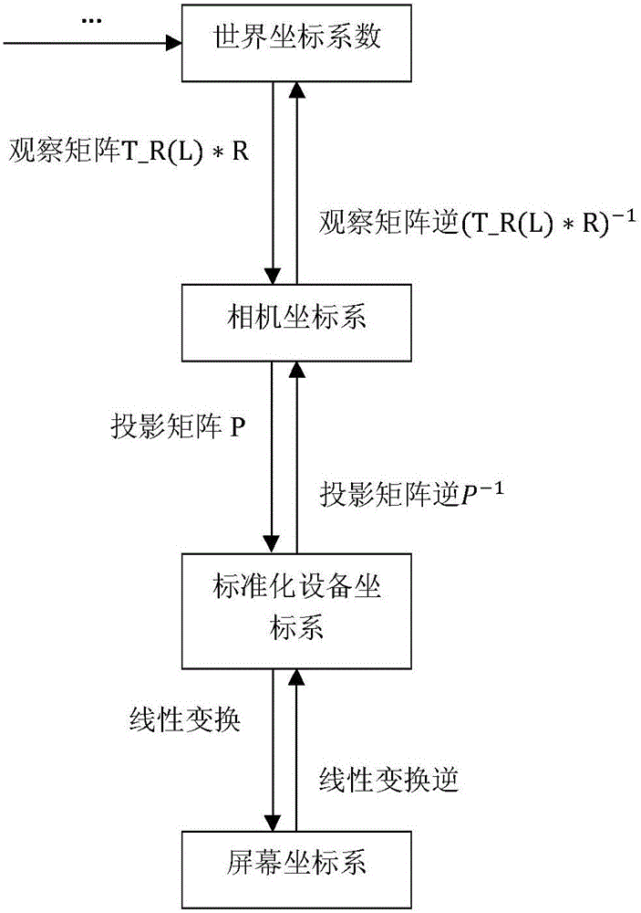
The invention discloses an image distortion method based on matrix inverse operation in a virtual reality (VR) mobile end. The method comprises the following steps: 1, reading a current frame and an equipment state; 2, converting coordinates under a screen coordinate system at current-frame time into coordinates under a standard equipment system at the current-frame time; 3, according to the coordinates under the standard equipment coordinate system at the current-frame time, obtaining coordinates in a world coordinate system; 4, according to the coordinates in the world coordinate system, obtaining coordinates under the standard equipment coordinate system at corresponding next-frame time; 5,performing linear transformation on the coordinates under the standard equipment coordinate system at the next-frame time so as to finally obtain coordinates under the screen coordinate system through the transformation; and 6, endowing the coordinates under the screen coordinate system at the corresponding next-frame time with pixel RGB values of the coordinates under the screen coordinate system at each current-frame time so as to obtain a final distortion image. The method is a method for generating intermediate frames in VR, can effectively reduce jittering in a VR game, and improves user experience.
Description
technical field [0001] The invention belongs to the fields of virtual reality, computer graphics, digital imageprocessing, etc., and relates to a method for image distortion in a virtual reality mobile terminal. method for the next frame. Background technique [0002] Virtual reality technology comprehensively utilizes computer graphics, photoelectric imaging technology, sensing technology, computer simulation, artificial intelligence and other technologies, and with the help of various interactive devices, it aims to provide users with a realistic and multi-sensory virtual world. [0003] In recent years, virtual reality technology has developed rapidly. With its powerful hardware, computer-side virtual reality technology has been able to bring users a good immersive experience. However, due to its high cost and cumbersome supporting equipment, it has not been widely popularized. . In contrast, the threshold of mobile virtual reality technology is low, because of the hig...
Claims
Application Information
Patent Timeline
Application Date:The date an application was filed.
Publication Date:The date a patent or application was officially published.
First Publication Date:The earliest publication date of a patent with the same application number.
Issue Date:Publication date of the patent grant document.
PCT Entry Date:The Entry date of PCT National Phase.
Estimated Expiry Date:The statutory expiry date of a patent right according to the Patent Law, and it is the longest term of protection that the patent right can achieve without the termination of the patent right due to other reasons(Term extension factor has been taken into account ).
Invalid Date:Actual expiry date is based on effective date or publication date of legal transaction data of invalid patent.

