
Bipolar wireless charging coil

A wireless charging and bipolar technology, applied in the direction of transformer/inductor coil/winding/connection, circuit, inductor, etc., can solve the problems of low transmission efficiency, easy to occur offset, large coil leakage inductance, etc., to improve Effects of transmission efficiency, enhanced excitation inductance, and reduced radiation

Inactive Publication Date: 2016-12-07
SHANGHAI JIAO TONG UNIV
View PDF6 Cites 30 Cited by
  • Summary
  • Abstract
  • Description
  • Claims
  • Application Information

AI Technical Summary

Problems solved by technology

Coils with common structures have large leakage inductance and low coupling coefficient, so the transmission efficiency is low
In addition, due to the charging process of electric vehicles, the receiving coil on the chassis of the car is not easy to align with the transmitting coil laid on the ground, and it is easy to shift
In this case, the coil transmission efficiency of the common structure will be further reduced

Method used


Image

  • Bipolar wireless charging coil
  • Bipolar wireless charging coil
  • Bipolar wireless charging coil

Examples


Embodiment Construction

[0026] The present invention will be described in detail below in conjunction with specific embodiments. The following examples will help those skilled in the art to further understand the present invention, but do not limit the present invention in any form. It should be noted that those skilled in the art can make several changes and improvements without departing from the concept of the present invention. These all belong to the protection scope of the present invention.

[0027] In the description of the present invention, it should be understood that the orientation or positional relationship indicated by the terms "upper", "lower", "left" and "right" are based on the orientation and positional relationship shown in the drawings, and are only for the convenience of describing the present invention. structure and mode of operation, rather than indicating or implying that the referred part must have a particular orientation or operate in a particular orientation, and thus ...


PUM


Abstract

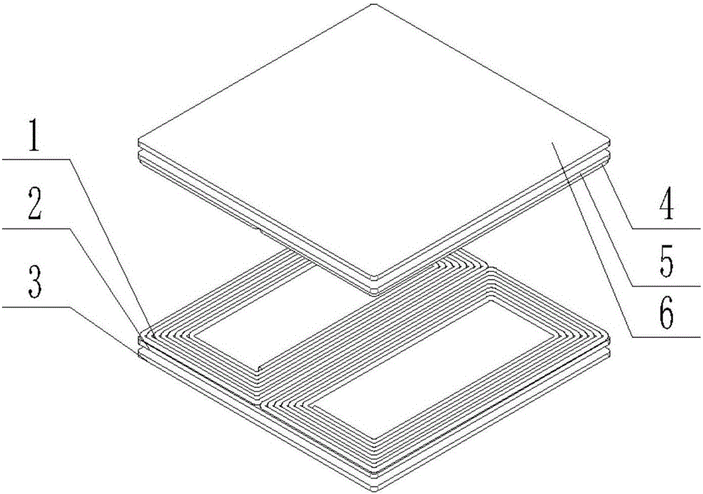
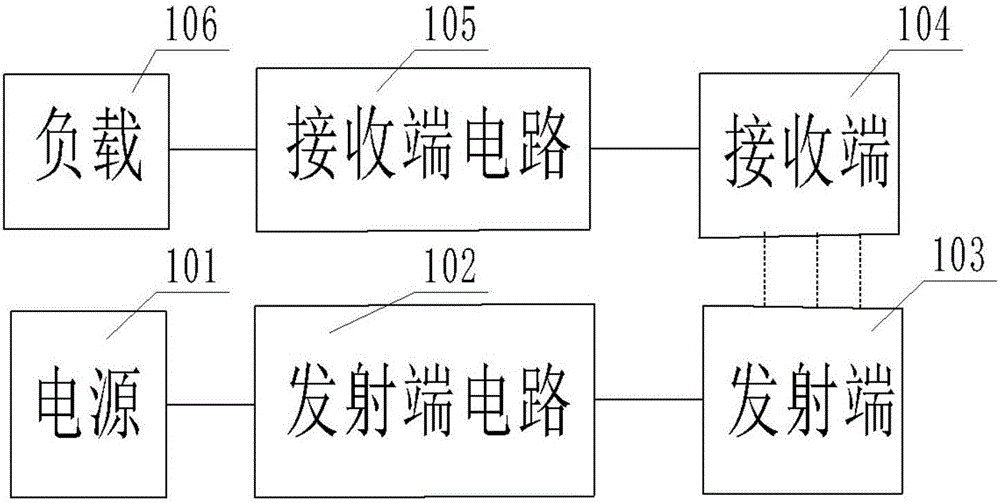
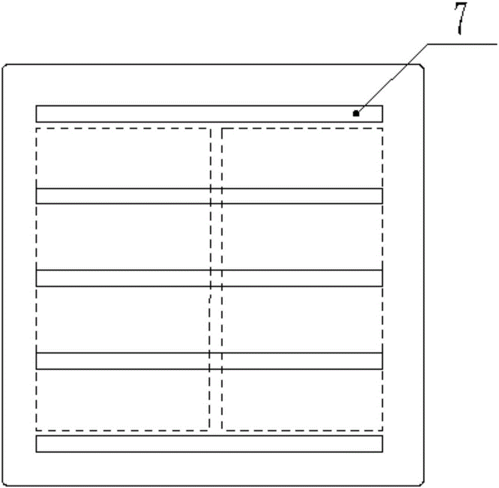
The invention provides a bipolar wireless charging coil, which comprises a transmitting terminal and a receiving terminal, wherein the transmitting terminal comprises a transmitting terminal magnetic shielding layer, a transmitting terminal magnetic dielectric layer, a transmitting terminal support layer and a transmitting coil layer which are sequentially arranged; the receiving terminal comprises a receiving coil layer, a receiving terminal support layer, a receiving terminal magnetic dielectric layer and a receiving terminal magnetic shielding layer which are sequentially arranged; and the transmitting coil layer and the receiving coil layer are coupled to each other and are symmetrical in structure. The magnetic field coupling degree of the transmitting terminal and the receiving terminal is relatively high during wireless charging; the quality factors of the transmitting terminal and the receiving terminal are relatively low; the power transmission efficiency is improved; the bipolar wireless charging coil is suitable for high-power wireless charging; and meanwhile, magnetic field radiation to surroundings can be reduced by the coil structure, so that the transmission efficiency can be improved.

Description

technical field [0001] The present invention relates to the technical field of wireless power transmission, in particular, to a bipolar wireless charging coil. Background technique [0002] In recent years, with the continuous development of power electronics technology, the efficiency and power of wireless charging systems have been continuously improved, and the application range has been continuously expanded. One of the main applications of wireless charging at present is the field of electric vehicles. Due to the bottleneck of battery technology, compared with internal combustion engine vehicles, electric vehicles have problems that cannot be solved in the short term, such as short battery life and high cost. Using wireless charging technology can avoid the technical problems of batteries. By laying the transmitting coil underground and fixing the receiving coil on the chassis of the electric vehicle, the electric vehicle can be charged in the parking lot or while dri...

Claims


Application Information

Patent Timeline
IPC IPC(8): H01F38/14H01F27/24H01F27/28H01F27/30H01F27/36H02J50/10
CPCH01F27/24H01F27/2871H01F27/306H01F27/36H01F38/14
Inventor 张希张智敏赖梓扬
Owner SHANGHAI JIAO TONG UNIV
Learn More