
Digital pulse width modulator based on DCM (Digital Clock Manager) modulation

A technology of width modulation and digital pulse, applied in the electronic field, can solve the problems of high cost, complex structure and composition, high design process requirements, etc., and achieve the effect of low cost, simple and easy to implement design, and high modulation accuracy

Inactive Publication Date: 2016-12-07
NANJING UNIV OF AERONAUTICS & ASTRONAUTICS +1
View PDF5 Cites 8 Cited by
  • Summary
  • Abstract
  • Description
  • Claims
  • Application Information

AI Technical Summary

Problems solved by technology

However, this method has the following disadvantages: the basic clock signal frequency of this method is only 1MHz, and its structure is complex, the design process requirements are high, and the cost is relatively high

Method used


Image

  • Digital pulse width modulator based on DCM (Digital Clock Manager) modulation
  • Digital pulse width modulator based on DCM (Digital Clock Manager) modulation
  • Digital pulse width modulator based on DCM (Digital Clock Manager) modulation

Examples


Embodiment Construction

[0022] The present invention will be described in further detail below with reference to accompanying drawing.

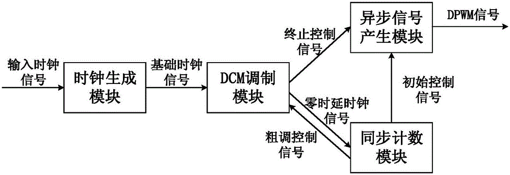
[0023] The present invention provides a high-precision digital pulse width modulator, such as figure 1 As shown, the digital pulse width modulator is composed of a clock generation module, a synchronous counting module, a DCM modulation module and an asynchronous signal generation module. The specific circuit diagram of the four modules is as follows Figure 2 to Figure 5 Shown.

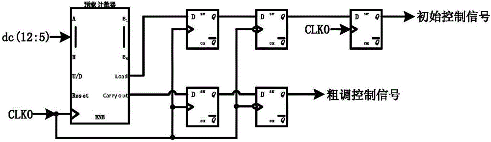
[0024] First, divide the input 13-bit array dc(12:0) into high 8-bit array N=dc(12:5) and low 5-bit array m=dc(4:0).

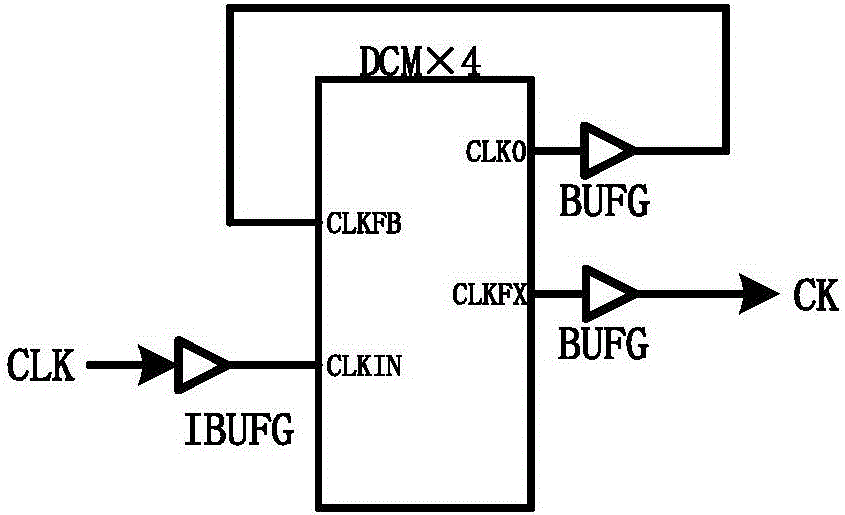
[0025] exist figure 2 In the clock generation module shown, DCM×4 is a 4-fold frequency multiplier. The CLK signal is an input clock signal with a frequency of 50MHz. After the CLK clock signal is multiplied by DCM×4, the output frequency is a basic clock signal with a frequency of 200MHz. From CK to DCM0 of the DCM modulation module, DCM0 outputs the zero-delay clock ...


PUM


Abstract

The invention discloses a digital pulse width modulator based on DCM (Digital Clock Manager) modulation. A clock generation module outputs a basic clock signal to a DCM modulation module after performing frequency multiplication on an input clock signal; a synchronous counting module realizes rough modulation of a pulse width by accurately counting zero time delay clock signals, and outputs an initial control signal and a rough modulation control signal to an asynchronous signal generation module and the DCM modulation module respectively at the start and end of the counting; the DCM modulation module outputs a zero time delay clock signal of the basic clock signal to the synchronous counting module, realizes accurate time delay on the basic clock signal at the same time, performs accurate time delay on the rough modulation control signal under the control of a time delay clock signal, and outputs a termination control signal to the asynchronous signal generation module; and the initial control signal and the termination control signal are input into the asynchronous signal generation module, and a final DPWM (Digital Pulse Width Modulation) signal is output. Through adoption of the digital pulse width modulator, accurate phase time delay for the basic clock signal is realized based on the DCM modulation; the modulation accuracy is increased under the condition of constant basic clock signal; and relatively high accuracy, universality and applicability are achieved.

Description

technical field [0001] The invention belongs to the field of electronic technology, and in particular relates to a digital pulse width modulation circuit. Background technique [0002] In the system structure using digital pulse width modulation (Digital Pulse Width Modulation, DPWM), the main methods currently used are hybrid DPWM (Hybrid DPWM), and the second is DPWM realized by Dither method. The DPWM implemented by the Dither method is mainly realized by the idea of ​​​​the design. This design can use a low-precision and high-frequency DPWM to achieve a high effective output accuracy, which also reduces the power consumption and area of ​​​​the DPWM. However, the DPWM realized by the Dither method will generate a cycle delay when the mode is switched, which is not good for the high-speed response of the DPWM, and the design of the hybrid DPWM has no unnecessary delay. [0003] The hybrid DPWM combines the traditional counter structure and the delay chain structure, and ...

Claims


Application Information

Patent Timeline
IPC IPC(8): H03K7/08
CPCH03K7/08
Inventor 胡文戴祥胡姗姗庄珊娜袁效鹏齐全陆晓明陈悦朱熠良
Owner NANJING UNIV OF AERONAUTICS & ASTRONAUTICS
Features
  • Generate Ideas
  • Intellectual Property
  • Life Sciences
  • Materials
  • Tech Scout
  • Unparalleled Data Quality
  • Higher Quality Content
  • 60% Fewer Hallucinations
Learn More