
Eye protection method and device for wireless optical link

A wireless optical and wireless optical technology, applied in the field of optical communication, can solve the problems of reducing transmission efficiency, reducing transmission range, etc., to achieve the effect of reducing transmission efficiency, avoiding damage, and being easy to implement

Inactive Publication Date: 2016-12-07
钱浙滨
View PDF7 Cites 1 Cited by
  • Summary
  • Abstract
  • Description
  • Claims
  • Application Information

AI Technical Summary

Problems solved by technology

[0025] The present invention provides a wireless optical link eye protection method and device, which are used to overcome at least the disadvantages of reduced transmission range, reduced transmission efficiency, and the need to wear an eye protection device when the existing laser eye protection technology is applied to the FSO system. A sort of

Method used


Image

  • Eye protection method and device for wireless optical link
  • Eye protection method and device for wireless optical link
  • Eye protection method and device for wireless optical link

Examples


Embodiment 1

[0053] Embodiment 1, an example of a wireless optical link eye protection method

[0054] see figure 1 As shown, an example of the wireless optical link eye protection method provided by the embodiment of the present invention includes the following steps:

[0055] Step S110, send an ultrasonic detection signal to the first adjacent area of ​​the laser beam propagation channel, and use the reflected wave or direct wave of the ultrasonic detection signal to detect the target, when it is detected that there is a target in the first adjacent area. After that, the emission of the corresponding laser beam is interrupted; and / or

[0056] Step S120: Receive a laser signal or radio feedback signal from the second / first wireless optical communication node side at the first / second wireless optical transmission node side, and use the laser signal or radio feedback signal to determine the relationship between the first wireless optical transmission node and the first wireless optical tra...

Embodiment 2

[0111] Embodiment 2, an example of a wireless optical link eye protection device

[0112] An example of the wireless optical link eye protection device provided by the embodiment of the present invention includes:

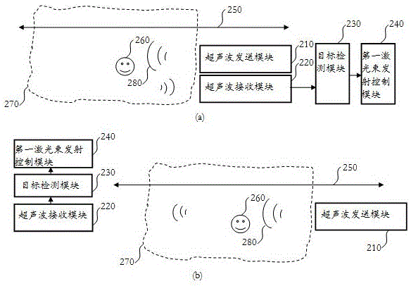
[0113] see figure 2 As shown in (a) / (b), the ultrasonic sending module 210, the ultrasonic receiving module 220, the target detection module 230, the first laser beam emission control module 240; and / or

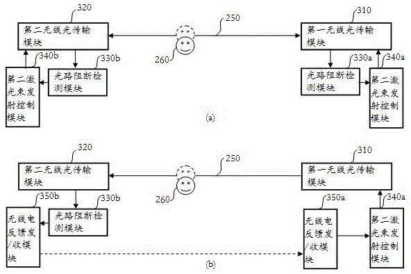
[0114] see image 3 As shown in (a), the first wireless optical transmission module 310, the second wireless optical transmission module 320, the optical path blocking detection module 330a / b, and the second laser beam emission control module 340a / b; preferably, see image 3 As shown in (b), the radio feedback sending / receiving module 350a / b is included;

[0115] in,

[0116] The ultrasonic sending module 210 is used to send the ultrasonic detection signal 280 to the first adjacent area 270 of the laser beam propagation channel 250, including an electro-acou...


PUM


Abstract

The invention discloses an eye protection method and device for a wireless optical link to overcome at least one of the defects that the existing technology reduces the transmission range and efficiency and needs to wear an eye protection device. The method comprises the following steps of sending an ultrasonic detection signal to a first adjacent region of a laser beam propagation channel, utilizing reflected wave or direct wave of the ultrasonic detection signal to carry out target detection and interrupting emission of the corresponding laser beam after detecting a target in the first adjacent region; and / or receiving a laser signal or a radio feedback signal from a second / first wireless optical communication node side at a first / second wireless optical transmission node, utilizing the laser signal or the radio feedback signal to determine whether a light path between the first wireless optical transmission node and the second wireless optical transmission node is blocked, and interrupting laser emission of the first / second wireless optical transmission node after determining that the light path is blocked. According to the method and the device, the damage of the laser link to eyes can be avoided, and the method and the device are easily realized.

Description

technical field [0001] The invention relates to the field of optical communication, in particular to a method and device for eye protection of a wireless optical link. Background technique [0002] Wireless optical communication or free space optical communication (FSO: Free Space Optical) has the characteristics of no frequency license, bandwidth, low cost, good confidentiality, flexible layout, and anti-electromagnetic interference. In addition, using the free-space optical communication system to establish a wireless optical link has the following advantages: 1) It is transparent to the running protocol, and the transmission control protocols commonly used in existing communication networks can be carried; 2) It can form point-to-point, star, 3) It is easy to expand and upgrade, and the capacity can be changed with only a slight interface change. [0003] Existing wireless optical communication systems include FSO systems based on direct coupling of photodetectors and FS...

Claims


Application Information

Patent Timeline
Patent Type & Authority Applications(China)
IPC IPC(8): H04B10/112H04B10/077H04B11/00
Inventor 钱浙滨
Owner 钱浙滨
Learn More