Video rendering method and device

A technology of video and equipment, applied in the field of display, can solve the problems affecting the efficiency of rendering, and there is no explanation for distinguishing processing, etc.

Inactive Publication Date: 2016-12-07
ZHEJIANG DAHUA TECH CO LTD
View PDF7 Cites 38 Cited by
  • Summary
  • Abstract
  • Description
  • Claims
  • Application Information

AI Technical Summary

Problems solved by technology

However, this method needs to create user-mode threads separately for image rendering and exchange, which inevitably requires a mutex or semaphore between threads to implement a thread sync

Method used


Image

  • Video rendering method and device
  • Video rendering method and device
  • Video rendering method and device

Examples


Embodiment Construction

[0036] In order to make the purpose, technical solutions and advantages of the present invention clearer, the present invention will be further described in detail below in conjunction with the accompanying drawings. Obviously, the described embodiments are only some of the embodiments of the present invention, rather than all of them. Based on the embodiments of the present invention, all other embodiments obtained by persons of ordinary skill in the art without making creative efforts belong to the protection scope of the present invention.

[0037] Embodiments of the present invention provide a video rendering method and device, which are used to reduce CPU performance loss during video rendering.

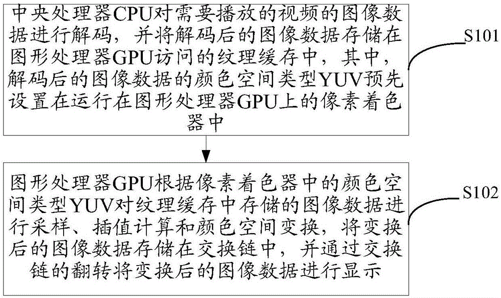
[0038] see figure 1 , a video rendering method provided in an embodiment of the present invention, the method comprising:

[0039] S101, the central processing unit CPU decodes the image data of the video to be played, and stores the decoded image data in the texture cache acce...


PUM


Abstract

The present invention discloses a video rendering method and device, which aim to lower central processing unit (CPU) performance loss in video rendering. The video rendering method comprises the steps that the CPU decodes image data of a to-be-played video, and stores the decoded image data in a pattern cache accessed by a graphics processing unit (GPU), wherein a color space type YUV of the decoded image data is preset in a pixel shader running on the GPU; and the GPU performs sampling, interpolation calculation and color space conversion on the image data stored in the pattern cache according to the color space type YUV in the pixel shader, and stores the converted image data in an exchange chain, and the converted image data is displayed through overturn of the exchange chain.

Description

technical field [0001] The present invention relates to the field of display technology, in particular to a video rendering method and device. Background technique [0002] Rendering is the last process when making animation or still frame works. It is the process of using the renderer to color the objects according to the parameter settings of the objects set in the scene. Rendering is an important link in the production process. [0003] Specifically, a complete image data processing flow includes the following steps: image acquisition, data encoding, network transmission, data decoding, and rendering and display. The image acquisition and data encoding are located at the sending end, and the encoded data reaches the receiving end after being transmitted through the network, and the receiving end is responsible for decoding and rendering the image data so as to be presented on the monitor. At the receiving end, the decoded image data is represented by a specific color spa...

Claims


Application Information

Patent Timeline
IPC IPC(8): H04N21/44H04N9/69
CPCH04N21/44012H04N9/69
Inventor 康宇宏
Owner ZHEJIANG DAHUA TECH CO LTD
Why Eureka
Try Eureka