
Joint downlink beam forming and unit attaching method in cloud radio access network

A wireless access network and wireless access network technology, which is applied in network planning, access restriction, wireless communication, etc., can solve problems that cannot be applied, can not really effectively reduce network energy consumption, and do not consider circuit energy consumption factors, etc.

Active Publication Date: 2016-12-07
BEIJING UNIV OF POSTS & TELECOMM
View PDF2 Cites 3 Cited by
  • Summary
  • Abstract
  • Description
  • Claims
  • Application Information

AI Technical Summary

Problems solved by technology

[0005] Document 1: Group sparse beamforming method for green cloud wireless access network, by minimizing weighted l 1 / l 2 Norm, proposed a joint beamforming and cell attachment method based on group sparsity to reduce the network energy consumption of C-RAN; however, the problem of limited fronthaul capacity was not considered, making this scheme unable to be applied to practical networks middle;
[0006] Document 2: Aiming at the joint beamforming and access control scheme of cloud wireless access network with limited forward link, a compromise scheme between transmission energy consumption and fronthaul transmission information volume is proposed, and a weighted l 1 Norm heuristic solution algorithm; this scheme only focuses on reducing transmission energy consumption, and does not consider the circuit energy consumption factor, that is, the cell attachment state, so this scheme cannot really effectively reduce network energy consumption

Method used


Image

  • Joint downlink beam forming and unit attaching method in cloud radio access network
  • Joint downlink beam forming and unit attaching method in cloud radio access network
  • Joint downlink beam forming and unit attaching method in cloud radio access network

Examples


Embodiment Construction

[0074] The present invention will be further described in detail below in conjunction with the accompanying drawings.

[0075] In the existing network energy consumption, circuit energy consumption accounts for a large proportion, so it is necessary to introduce cell attachment technology to control the status (active or dormant) of the base station (or RRH) when considering the issue of network energy conservation. Compared with the existing solutions, the present invention proposes a method of joint downlink beamforming and cell attachment, firstly introduces the network system model, then describes the specific method of joint downlink beamforming and cell attachment, and finally gives the performance of the method Simulation; in order to effectively reduce the transmission energy consumption and circuit energy consumption, while taking into account the user's service quality requirements, the maximum transmission power limit and the capacity limit of the fronthaul, effectiv...


PUM


Abstract

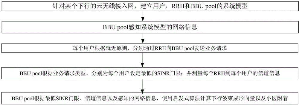
The invention discloses a joint downlink beam forming and unit attaching method in a cloud radio access network, belonging to the field of mobile communication. The joint downlink beam forming and unit attaching method specifically comprises the following steps: (1), for a certain downlink cloud radio access network, system models of users, an RRH and a BBU pool are established; (2), the BBU pool perceives network information of the system models; (3), various users respectively send service requests to the BBU pool through the RRH according to a proximity principle; (4), the BBU pool respectively sets the lowest SINR thresholds for various users according to the types of the service requests, and measures information of a channel from each RRH to each user; and (5), the BBU pool calculates a downlink beam forming vector and unit attachment by using a heuristic algorithm according to the lowest SINR thresholds, the channel information and the perceived network information. The joint downlink beam forming and unit attaching method disclosed by the invention has the advantages that: due to joint downlink beam forming and unit attaching, the network energy consumption can be effectively reduced; the purpose of saving energy is achieved; and simultaneously, the user service quality is ensured.

Description

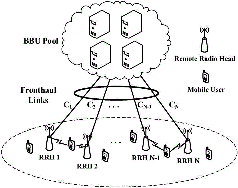
technical field [0001] The invention belongs to the field of mobile communication, and in particular relates to a method for joint downlink beamforming and cell attachment under a cloud wireless access network. Background technique [0002] Cloud Radio Access Network (Cloud Radio Access Network, C-RAN) is a strong candidate network architecture for 5G, such as figure 1 As shown, by separating the traditional base station into a remote radio unit (RRH, Remote RadioHead) closer to the user and a centralized baseband processing unit pool (BBU pool, Baseband Processing Unit pool), wherein the RRH is responsible for providing the user with Send data processed by the BBU pool, or receive user data and hand it over to the BBU pool for processing; BBUpool is the central processing unit in the C-RAN, responsible for information collection, processing, etc.; realizes centralized processing of baseband information, cooperative radio and real-time Cloud computing greatly improves syste...

Claims


Application Information

Patent Timeline
IPC IPC(8): H04W16/22H04W48/04H04W48/16H04B7/06
CPCH04B7/0617H04W16/22H04W48/04H04W48/16Y02D30/70
Inventor 王珂余智纪红李曦张鹤立
Owner BEIJING UNIV OF POSTS & TELECOMM
Learn More