
Light control module

A lighting control and lighting technology, applied in the direction of light source, electric light source, electric light circuit layout, etc., can solve the problems of large wiring volume of lighting control module, reduced electrical system stability, large space occupation, etc., to save labor and material costs, The effect of saving wiring space and wiring volume and reducing the failure rate

Inactive Publication Date: 2016-12-07
MCC BAOSTEEL TECH SERVICE
View PDF7 Cites 8 Cited by
  • Summary
  • Abstract
  • Description
  • Claims
  • Application Information

AI Technical Summary

Problems solved by technology

[0005] In view of the above-mentioned shortcomings of the prior art, the purpose of the present invention is to provide a lighting control module, which is used to solve the problems of complex wiring, lower stability of the electrical system, and overall The lighting control module has a lot of wiring and takes up a lot of space

Method used


Image

  • Light control module
  • Light control module
  • Light control module

Examples


Embodiment Construction

[0046] The implementation of the present invention will be illustrated by specific specific examples below, and those skilled in the art can easily understand other advantages and effects of the present invention from the contents disclosed in this specification.

[0047] see Figure 1 to Figure 6 . It should be noted that the structures, proportions, sizes, etc. shown in the drawings attached to this specification are only used to match the content disclosed in the specification, for those who are familiar with this technology to understand and read, and are not used to limit the implementation of the present invention. Limiting conditions, so there is no technical substantive meaning, any modification of structure, change of proportional relationship or adjustment of size, without affecting the effect and purpose of the present invention, should still fall within the scope of the present invention. The disclosed technical content must be within the scope covered. At the sa...


PUM


Abstract

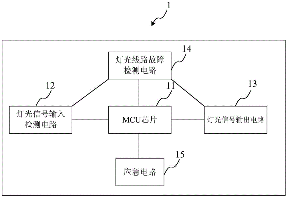
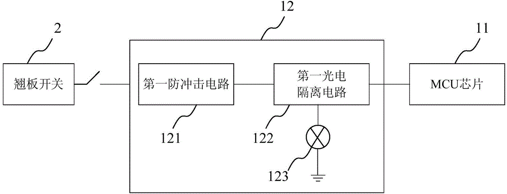
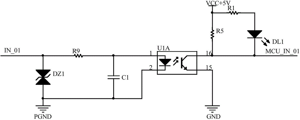
The invention provides a light control module, which comprises an MCU chip, a light signal input detection circuit, a first photoelectric isolation circuit, a first indication lamp, a light signal output circuit, and a light circuit fault detection circuit, wherein the MCU chip is used for controlling input and output of light signals and fault detection; the light signal input detection circuit comprises a first anti-impact circuit for eliminating input spikes and preventing voltage impact; the first photoelectric isolation circuit is used for isolating high voltage signals in the light signals and then inputting the light signals to the MCU chip; the first indication lamp is used for indicating the light signals; the light signal output circuit outputs corresponding light signals according to the instruction of the MCU chip; and the light circuit fault detection circuit at least comprises a current detection chip for determining fault of the light circuit through detecting current changes in the light circuit. Problems of complicated wiring in the case of circuit fault detection on the light control module, reduced electrical system stability, and a large wiring amount and large occupied space of the whole light control module can be effectively solved.

Description

technical field [0001] The invention relates to the technical field of electronic circuits of mechanical equipment, in particular to the technical field of lighting control for tank trucks, specifically a lighting control module. Background technique [0002] The tanker is a kind of metallurgical wheeled transportation equipment, and its working environment is complex and harsh. Lighting is an essential lighting and model equipment for tank trucks. There are 12 lights including left and right steering, high beam, low beam, small light, brake, reversing, fog lights, front and rear work lights, auxiliary work lights, and warning lights. Special warning lamps will also be added in more complicated or dusty areas to ensure the safe production of tank trucks and other equipment. [0003] With the development of power electronics technology, the electrical system is becoming more and more intelligent and informatized. The electrical system of the tank truck not only needs to real...

Claims


Application Information

Patent Timeline
Patent Type & Authority Applications(China)
IPC IPC(8): H05B37/02
Inventor 邵可耿会良谢明陈俊
Owner MCC BAOSTEEL TECH SERVICE
Learn More