ASM adjustable steel mesh clamping device

A clamping device and adjustable technology, applied in the direction of assembling printed circuits with electrical components, electrical components, printed circuit manufacturing, etc., can solve problems such as reducing the working efficiency of SMT printing machines, unable to locate the stencils of printing machines, and increasing maintenance costs. , to achieve the effect of easy maintenance, low equipment purchase cost and low maintenance cost

Active Publication Date: 2016-12-07
东莞市九方电子设备有限公司
View PDF6 Cites 1 Cited by
  • Summary
  • Abstract
  • Description
  • Claims
  • Application Information

AI Technical Summary

Problems solved by technology

[0003] 1. When assembling, it is necessary to thread a drawstring and connect the drawstring to each pressing block, so the assembly process is very cumbersome, time-consuming, inefficient, and inconvenient to assemble;
[0004] 2. During use, the pull rope is prone to breakage, which causes the stencil of the printing machine to be unable to be positioned, and the pull rope needs to be re-threaded. The maintenance time generally takes two hours, so the maintenance is very time-consuming, and the maintenance cost is greatly increased. At the same time, it still leads to a great reduction in the working efficiency of the SMT printing machine.
[0005] There is also an ASM adjustable stencil clamping device for printing solder paste or red glue on a printed circuit board, which includes a first support frame and a second support frame, and the first support frame and the second support frame are respectively installed There are a number of compression cylinders, which are used to drive the pressure plate to position the steel mesh of the printing machine. Due to the use of multiple compression cylinders, the equipment purchase cost is high and maintenance is inconvenient

Method used


Image

  • ASM adjustable steel mesh clamping device
  • ASM adjustable steel mesh clamping device
  • ASM adjustable steel mesh clamping device

Examples


Embodiment Construction

[0021] In order to understand the above-mentioned purpose, features and advantages of the present invention more clearly, the present invention will be further described in detail below in conjunction with the accompanying drawings and specific embodiments.

[0022] In the following description, more specific details are set forth in order to fully understand the present invention. However, the present invention can also be implemented in other ways different from those described here. Therefore, the protection scope of the present invention is not limited by the following disclosure. Limitations of specific embodiments.

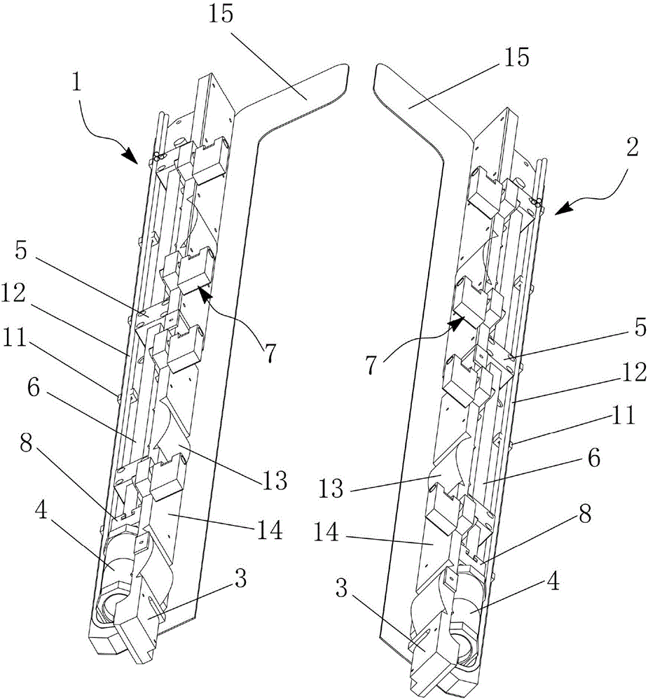
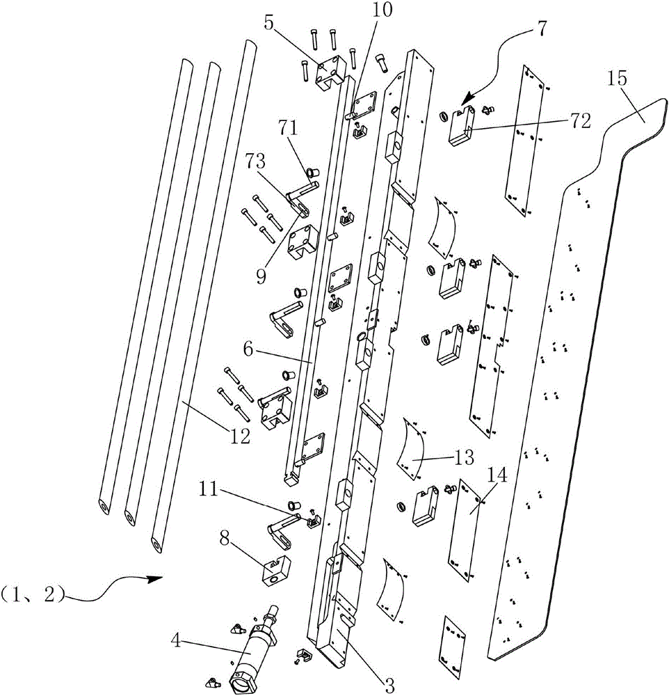
[0023] refer to figure 1 , 2 , providing an ASM adjustable steel mesh clamping device, including a first positioning mechanism 1 and a second positioning mechanism 2 oppositely arranged, and the first positioning mechanism 1 and the second positioning mechanism 2 respectively include a steel mesh positioning frame 3. The driving device 4 installed at one e...


PUM


Abstract

The invention discloses an ASM adjustable steel mesh clamping device. The device comprises a first positioning mechanism and a second positioning mechanism opposite to the first positioning mechanism. The first positioning mechanism and the second positioning mechanism both comprise a steel mesh positioning rack, a driving device erected at one end of the steel mesh positioning rack, at least one guide block erected on the steel mesh positioning rack, a transmission connection rod which is erected on the guide block and in transmission connection with the driving device, and at least one clamping unit which is erected on the steel mesh positioning rack and in transmission connection with the transmission connection rod. Each positioning mechanism only needs one driving cylinder to drive multiple clamping units to precisely position an ASM adjustable steel mesh. The device has the advantages of being high and stable in positioning precision, high in printing precision and high in production efficiency. The ASM adjustable steel mesh clamping device is very easy to assemble, assembly time is short, efficiency is high, equipment purchasing cost is low, service life is long, later maintenance is easy, and time for maintenance is short.

Description

technical field [0001] The invention relates to the field of surface mount technology (SMT), and more specifically relates to an ASM adjustable steel mesh clamping device. Background technique [0002] ASM (Adjustable Stencil Mount, adjustable stencil mount), the ASM adjustable stencil clamping device traditionally used for printing solder paste or red glue on printed circuit boards includes a first support frame and a second support frame, The first support frame and the second support frame are equipped with pull rope cylinders, several briquetting blocks and pull ropes respectively. Rotate the connection, tighten the stay rope through the stay rope cylinder to make the first pressing block move down to compress the steel mesh. The stencil positioning device of this type of structure has the following defects: [0003] 1. When assembling, it is necessary to thread a drawstring and connect the drawstring to each pressing block, so the assembly process is very cumbersome, ...

Claims


Application Information

Patent Timeline
Patent Type & Authority Applications(China)
IPC IPC(8): H05K3/30
CPCH05K3/303H05K2203/0195
Inventor 罗安松汤志
Owner 东莞市九方电子设备有限公司
Why Eureka
Try Eureka