Funnel-shaped crystallizer copper plate mould of continuous casting sheet billet
A mold copper plate and funnel-type technology is applied in the production and use of continuous casting thin slab copper plate molds, which can solve problems such as affecting the service life and easy cracking of continuous casting billet copper plate molds, so as to improve the thermal conductivity and the overall transmission. The effect of heat capacity, the ability to improve heat transfer vapor resistance
- Summary
- Abstract
- Description
- Claims
- Application Information
AI Technical Summary
Problems solved by technology
Method used
Image

Examples
Embodiment 1
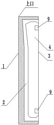
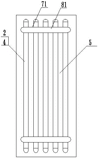
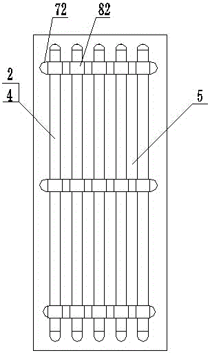
[0019] Embodiment one: if figure 1 , figure 2 , Figure 6 As shown, a continuous casting thin slab funnel-shaped crystallizer copper plate mold, which includes a funnel-shaped working surface 1 on the front, a cooling water tank 2 with cooling function and a cooling water tank surface 3 on the back, and inserting the cooling water tank 2 to control the cooling water tank 2 The cross-sectional size of the insert 4 also includes the ribs 5 between the cooling water tanks 2 and the water holes 6 on the ribs 5. The copper plate mold is called the upper part near the mouth of the funnel, and the opposite is called the lower part. The bar 4 is connected with two positioning mechanisms arranged on the upper and lower parts of the cooling water tank surface 3, and the cross-sectional area formed by the inlaid bar 4 and the cooling water tank 2 is fixed by the positioning mechanism.
[0020] The positioning mechanism is composed of a long keyway 71, a long key 81 and a slot 9 at the...
Embodiment 2
[0022] Embodiment 2: The difference between it and Embodiment 1 is: optimally, starting from the upper opening of the copper plate mold, until the distance from the upper opening is 250mm, the cross-sectional depth dimensions of each part of each insert are designed to match the depth of the corresponding part of the corresponding cooling water tank The size difference gradually increases by 15%. From the distance of 250mm from the upper mouth to the lower mouth of the copper plate mold, the difference between the depth dimension of each part of the section of each insert and the depth dimension of the corresponding part of the corresponding cooling water tank remains unchanged.
Embodiment 3
[0023] Embodiment 3: The difference from Embodiment 1 is: preferably, starting from the upper opening of the copper plate mold until the distance from the upper opening is 300mm, the design of the section depth of each part of each insert is the same as the depth of the corresponding part of the corresponding cooling water tank The difference in size gradually increases by 10%. From 300mm from the upper opening to the lower opening of the copper plate mold, the difference between the depth dimension of each part of the section of each insert and the depth dimension of the corresponding part of the corresponding cooling water tank remains unchanged.
PUM
 Abstract
Description
Claims
Application Information