
Vehicle lamp machining mold

A technology for processing molds and car lights, which is applied to household appliances, other household appliances, household components, etc. It can solve the problems that the injection material cannot enter the cavity, the product has poor structural strength, and the direction is difficult to control, etc., and achieves good preheating effect , compact structure, small footprint

Inactive Publication Date: 2016-12-14
JIANGSU YUYAN MOLD IND
View PDF0 Cites 9 Cited by
  • Summary
  • Abstract
  • Description
  • Claims
  • Application Information

AI Technical Summary

Problems solved by technology

Automobile lights are generally completed by mold casting. The original casting molds mainly have the following disadvantages: 1. The movable and fixed templates of the existing casting molds are generally arranged on the frame, and the jacking cylinders are also installed on the frame. On the frame, the structure is relatively loose and takes up a lot of space; 2. The casting channel of the existing casting mold is generally a vertical channel connected with the die, and the structure is relatively simple. The channel enters the mold cavity, and the pouring diameter connected with the die is relatively large, so it is difficult to control the direction of the injection material into the cavity, resulting in poor structural strength of the molded product; 3. The existing casting channel is unable to Preheating, the temperature of the casting channel is relatively low during the casting process, the injection material is easy to condense instantly when it enters the casting channel, and the injection material cannot enter the cavity, resulting in production stagnation and high maintenance rate

Method used


Image

  • Vehicle lamp machining mold

Examples


Embodiment Construction

[0009] The specific content of the present invention will be described in detail below in conjunction with the accompanying drawings and specific embodiments.

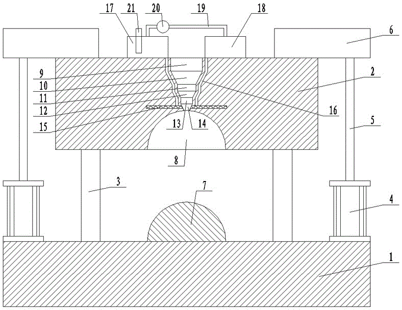
[0010] Such as figure 1 As shown, the automobile lamp processing mold includes: a fixed template 1 and a movable template 2, and the fixed template

[0011] 1 is provided with a guide column 3, and the movable template 2 is slidably arranged on the guide column 3, and a jacking cylinder 4 is arranged on the fixed template 2 at the lower end of both sides of the movable template 2, and the piston rod 5 of the jacking cylinder 4 Connected with the upper end of the movable template 2 through the connecting block 6, a car lamp punch 7 is arranged in the middle of the upper end of the fixed template 1, and a car lamp punch 7 that cooperates with the car lamp punch 7 is provided in the middle of the lower end of the movable template 2. The car lamp die 8 is provided with a first-stage vertical injection channel 9, a first-s...


PUM


Abstract

The invention discloses a vehicle lamp machining mold. The vehicle lamp machining mold comprises a fixed template and a movable template; the fixed template is provided with a guide column; the movable template is slidingly arranged on the guide column; jacking cylinders are arranged on the fixed template at the lower ends of two sides of the movable template; piston rods of the jacking cylinders are connected with the upper ends of the movable template through connecting blocks; a vehicle lamp convex mold is arranged at the middle part of the upper end of the fixed template; a vehicle lamp concave mold matched with the vehicle lamp convex mold is arranged at the middle part of the lower end of the movable template; a first-grade vertical injection molding channel, a first-grade conical injection molding channel, a second-grade vertical injection molding channel, a second-grade conical injection molding channel, a third-grade vertical injection molding channel and a third-grade conical injection molding channel communicated with each other are arranged in the movable template at the upper end of the vehicle lamp concave mold in sequence from top to bottom; and the diameters of the first-grade vertical injection molding channel, the second-grade vertical injection molding channel and the third-grade vertical injection molding machine are gradually reduced.

Description

technical field [0001] The invention relates to a mold, in particular to a mold for processing automobile lamps. Background technique [0002] With the continuous advancement of science and technology and the rapid development of industry, as an industrial pillar industry, the automobile industry has made a huge contribution to my country's gross national product, and automobiles have gradually changed from the initial means of transportation to people's life and work. Travel and leisure tools. As an important part of a car, car lights have received people's attention in every detail during the production process. Automobile lights are generally completed by mold casting. The original casting molds mainly have the following disadvantages: 1. The movable and fixed templates of the existing casting molds are generally arranged on the frame, and the jacking cylinders are also installed on the frame. On the frame, the structure is relatively loose and takes up a lot of space; 2...

Claims


Application Information

Patent Timeline
Patent Type & Authority Applications(China)
IPC IPC(8): B29C39/26B29C39/38B29L31/30
CPCB29C39/26B29C39/38B29L2031/30
Inventor 孙从贵
Owner JIANGSU YUYAN MOLD IND
Learn More